Section 8- W6215, W7215 And W7460 Economizer Modules
63-8594-02 Honeywell Economizers 74
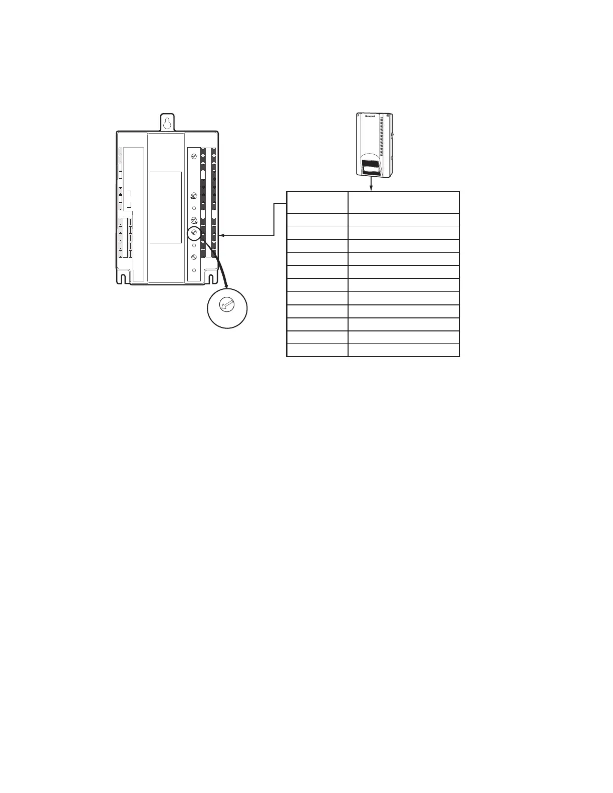
Indoor Air Content Sensor Settings
The DCV input can be any sensor with a 2 to
10 Vdc output such as the Honeywell C7242,
C7232 or C7632 carbon dioxide (CO
2
)sensor.
The sensor is supplied with preset
configurations that can be used if they meet
the application requirements. The output chart
illustrated on the right side of this page is the
Analog 1 configuration of startpoint and
throttling range for a linear output.
24VAC
TR Hot
24VAC
Com
24VAC
Hot
2-10V
OUT
Free
Cool
Unit
Control
Exhaust
Fan
Indoor
Fan
Mininum
Position
Maximum
Position
Open
Free Cooling
Close
ISI
OSI
OSI
Set Pt
2V
100%
6V
2V
6V
10V
ISI
Set Pt
A
BC
D
TR1
Com
+
+
5
2
4
1
T1
T
P1
Q1
AQ1
AQ
SD1
SD
AC1
AC
0A1
0A
So
Sr
W7215B
+
–
M23925A
+
–
Q
P
3
Alarm
C7242 INDOOR
AIR CONTENT
CO2 SENSOR
ECONOMIZER
MODULE WITH
DCV SENSOR INPUT
DCV SENSOR
INPUT ON
TEMINALS
AQ AND AQ1
2V
6V
10V
DCV
Set Pt
ROOM CONCENTRATION CARBON
DIOXIDE IN PARTS PER MILLION
500
650
800
950
1100
1250
1400
1550
1700
1850
2000
SENSOR OUTPUT
IN VOLTS DC
0
1
2
3
4
5
6
7
8
9
10
 Loading...


