ECS Device Installation 151455
4-3
4.2.3 Installing and Connecting the ECS-VCM to the ECS-SW24
The ECS-SW24 adds 24 switches to the IFP-100ECS, IFP-1000ECS, ECS-LOC, IFP-2000ECS
controls for a total of 40 (with the 16 Non-ECS switches on the ECS-VCM).
Follow these steps to install and connect the ECS-SW24:
1. Open Cabinet door and dead front panel.
2. Remove AC power from the main control panel.
3. Disconnect the backup batteries.
4. Install the ECS-SW24 on the six mounting studs located on the inside of the dead front panel. See
Figure 4-6 for IFP-100ECS and IFP-1000ECS or Figure 4-7 for IFP-2000ECS.
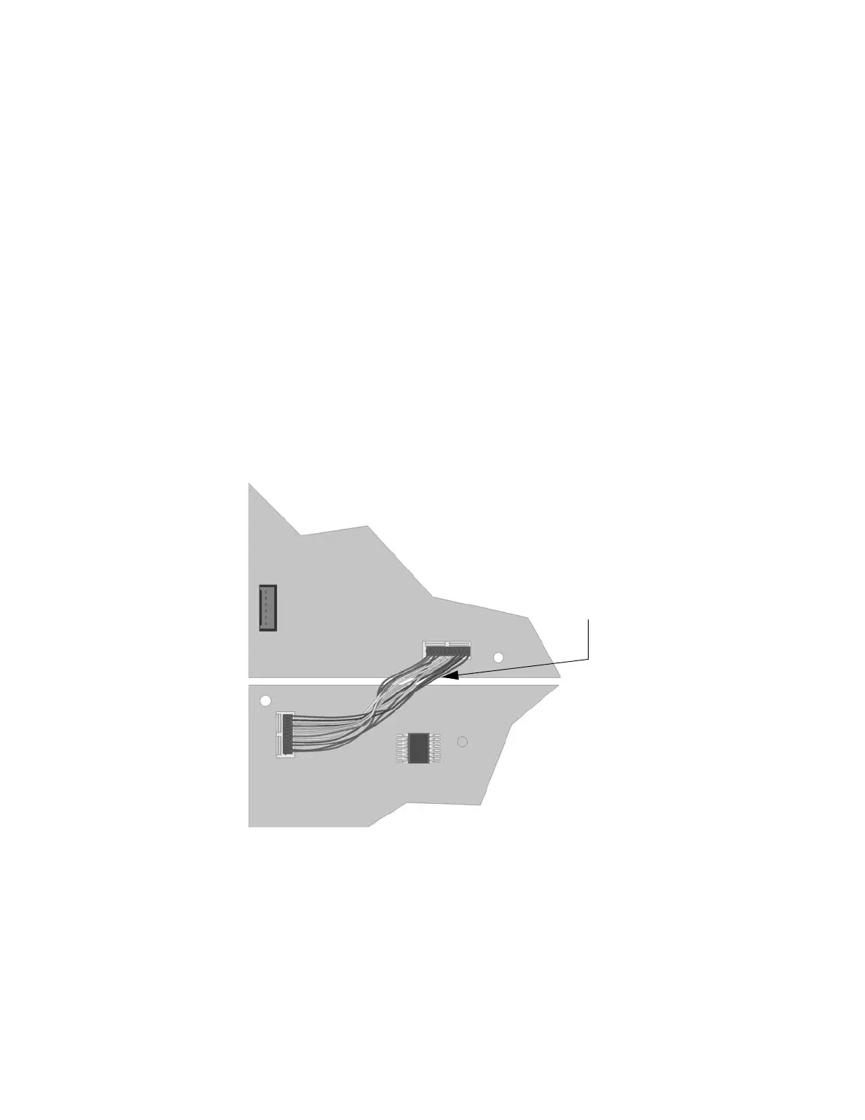
5. For the IFP-100ECs or IFP-1000ECS, Connect one end of the wiring harness (P/N 130398 sup-
plied) to the ECS-VCM and the other end to the ECS-SW24 as shown in Figure 4-4.
6. For IFP-2000ECS connect one end of the wiring harness (PN 130398 supplied) to the ECS-VCM,
and the other end to the ECS-SW24. If two ECS-SW24's are used, connect one ECS-SW24 to the
other ECS-SW24 as shown in Figure 4-5.
7. Secure the switch expander(s) to the dead front panel using the supplied six ¼” Hex nuts.
8. Restore AC power.
9. Reconnect backup batteries.
Figure 4-4 Wiring Harness Connection for VCM to One ECS-SW24
Wiring Harness
VCM
ECS-SW24

 Loading...


