ECS Series Emergency Communication System Installation Manual 151455
4-30
4.7 Installing the ECS-125W
This section provides information on how to install the ECS-125W for use with ECS-series products.
4.7.1 ECS-125W Board Layout
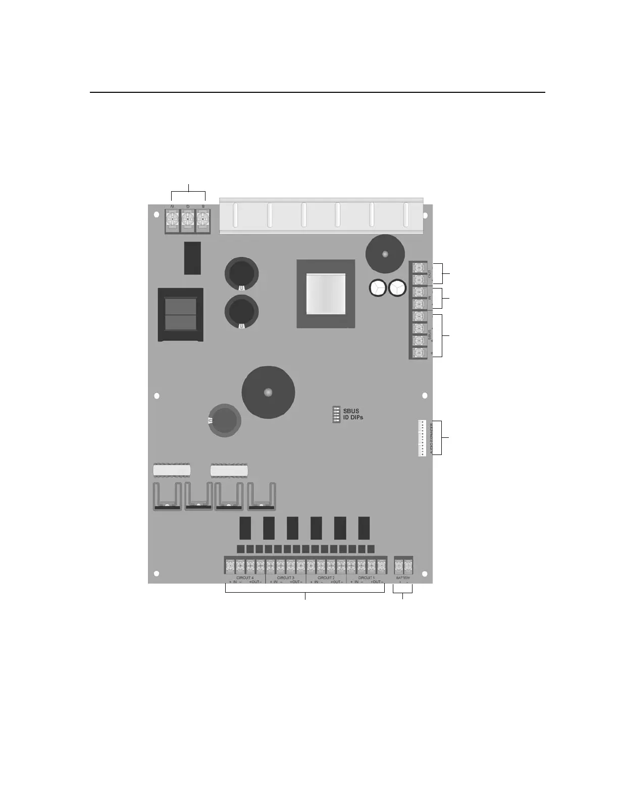
Figure 4-41 shows the location of terminals, DIPs, and Expander connections used in the installation of
the ECS-125W.
Figure 4-41 Components Layout of ECS-125W
AC Connector
VBUS Out
VBUS IN
SBUS
Audio
Expander
Audio Circuits
Battery
Connector
 Loading...


