LS10143-001SK-E IDP, SK, SD and SWIFT™ SLC Device Installation
7-6
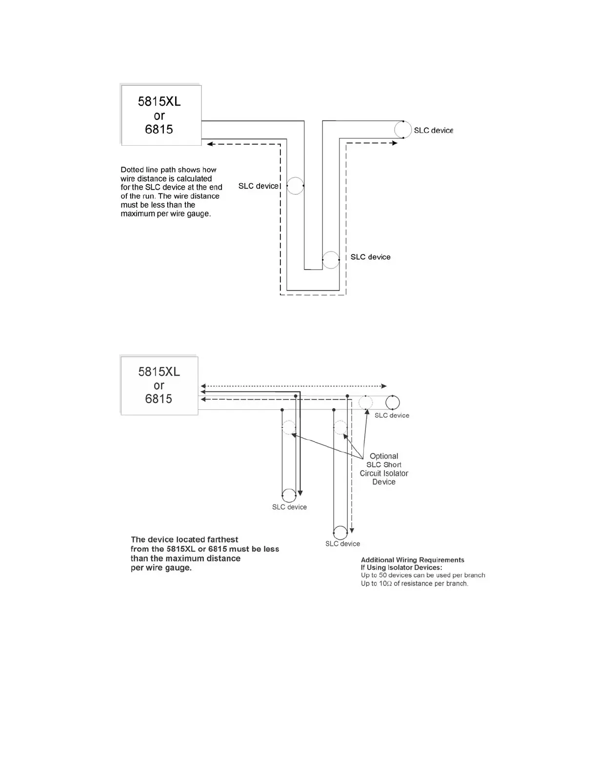
Figure 7-1 and Figure 7-2 show how wire length is determined for out & back tap and T-Tap.
Figure 7-1 Calculating wire run length for a simple out and back
When using T-taps, the total length of all taps and the main bus must not exceed 40,000 feet. This requirement
must be met in addition to the maximum distance requirements for the various wire gauges.
Figure 7-2 Calculating Wire Run Length for a T-tap
7.6.4 Wiring 5815XL or 6815 in Style 6 & 7 (Class A) Configuration
Figure 7-3 illustrates how to wire the SLC loop for Class A installations.
Note: Style 6 does not use short circuit isolator devices
Note: Style 7 requires an isolator module as the first device on the in and the out loop

 Loading...


