LS10143-001SK-E Control Panel Installation
4-38
detector to the control panel.
4.15.4.1 Installing a Class B 4-Wire Smoke Detectors
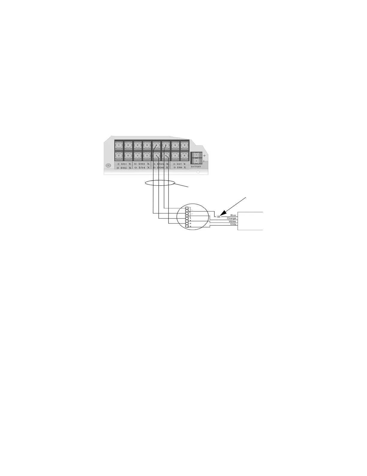
Figure 4-53 illustrates how to install a 4-wire Class B smoke detector.
Conventions used for wiring 4-wire Class B loops:
1. Up to four Class B 4-wire smoke detector loops can be connected to the control panel at once.
2. Each Class B loop input is paired with a unique power source as shown in Figure 4-53.
3. Each loop gets smoke power from the even numbered Flexput circuit and the contact input is connected to
the odd numbered Flexput circuit.
Figure 4-53 Class B 4-Wire Smoke Detector Connections
Note: In programming any point that uses multiple Flexput circuits, the lowest Flexput circuit number is used to
refer to the circuit pair. For example, Figure 4-53 uses both Flexput circuit 5 and 6, so in programming it
would be referred to as point 5.
4.15.4.2 Installing 4-Wire Class A Smoke Detectors
Figure 4-54 illustrates how to install 4-wire Class A detectors. Conventions used for wiring 4-wire Class A
loops:
1. Up to two Class A 4-wire loops can be connected to the control panel at once.
Air Products
PAM-2
Model 160150
Supervision
Module
EOL resistor
ESL 449CT
Note:
Flexput circuit 5 and 6
used as an example.
Any Flexput point pairing
could be used.
supervised
power limited
Maximum Impedance
per Circuit is 50Ω

 Loading...


