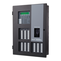
Model IFP-2100/ECS Installation Manual LS10143-001SK-E
1-1
Section 1
Introduction
The IFP-2100 (red) / IFP-2100B (black) and IFP-2100ECS (red) / IFP-2100ECSB (black) are analog addressable
fire alarm control panels (FACP), that meets the requirements of UL 864. The IFP-2100ECS is an analog
addressable fire control system combined with an Emergency Communication System that meet the
requirements for Mass Notification as described in UL 864 and UL 2572.
The RFP-2100 (red) or RFP-2100B (black) are the same as the IFP-2100 without the display. The RFP-2100 is
used in a networked system where there is at least one IFP-2100/ECS in the system. When using the RFP-2100
as a stand alone local unit, one LCD annunciator must be connected, and the annunciator must be wired in
conduit within 20’of the RFP-2100.
Note: All references to IFP-2100 or IFP-2100ECS within this manual are applicable to the IFP-2100B and IFP-
2100ECSB. All References to the IFP-2100HV are applicable to the IFP-2100HVB, RFP-2100HV, RFP-
2100HVB, IFP-2100ECSHV and the IFP-2100ECSHVB.
Note: All references to RFP-2100 within this manual are applicable to RFP-2100B.
1.1 Overview of Basic System
The IFP-2100/ECS base system is packaged as an assembled stack of 3 circuit boards mounted to an aluminum
housing.
1.1.1 Hardware Features
• The basic IFP-2100/ECS panel contains one built in signaling line circuit (SLC), which supports up to 159
IDP or SK sensors and 159 IDP or SK modules or 127 SD SLC devices. Additional SLC loops can be added
to increase overall point capacity.
• Additional 6815 SLC expanders supports 159 IDP or SK sensors and 159 IDP or SK modules for a
maximum of 2100 points per IFP-2100/ECS control panel.
• Additional 5815XL SLC expander supports only SD Protocol for a maximum of 2032 points per IFP-2100/
ECS control panel.
• 9.0A of output power is available through 8 sets of terminals for notification and auxiliary applications.
Each circuit is power limited per UL 864 and can source up to 3.0A (total output power must not exceed
9.0A). The constant auxiliary power load must not exceed 6.0A for normal standby.
• Built-in dual phone line, digital alarm communicator/transmitter (DACT), IP or optional cellular
technologies.
• Reports events to central station by point or by zone.
• UL Listed for pre-action and deluge releasing systems.
• Dedicated Form C trouble relay and two general purpose Form C programmable relays.
• Can be used with RA-2000s
1
, RA-1000s
2
or RA-100s
2
in any combination.
• Supports the 5865-3, 5865-4, and 5880 LED annunciators
1
. See sections 4.11 and 4.12 for additional
information on these models.
• Printing of event log available through the Model 5824
1
serial/parallel printer interface module.
• Supports conventional 2-wire & 4-wire detectors using the 8 Flexput™ circuits or SLC zone modules.
• 999 software zones, 999 output groups.
• Add four notification/auxiliary power circuits with each 5496 Intelligent Power Module.
• Add six Flexput™ circuits with each RPS-1000 Remote Power Supply.

 Loading...