INTELLIGUARD 9000™
74-3047—116
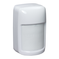
Keypad Control Centers (CC2)
Ke
pad Control Centers allow an operator to pro
ram user
information into the s
stem. This information can include area
armin
, partial armin
, disarmin
, new user IDs and removin
obsolete users. Each I9000 CU supports a maximum of four
CC2 control centers. The CC2 also displa
s information on an
LCD screen located at the top of the cover. Fi
. 16 shows
wirin
for a CC2.
Fig. 16. CC2 wiring.
NOTE: TB1-1 and TB1-2 connect to 12 Vdc whereas TB1-3
TxRx-
and TB1-4
TxRx+
connect to CU COM 1 or
2, but not both.
Because of the hi
h power re
uirements of the backli
htin
, it
is possible to disable it. This is especiall
useful in current
sensitive applications.
The backli
htin
is activated for five minutes followin
the
most recent of the followin
events:
— a ke
is pressed.
— a tone was tri
ered from the control unit.
To install the Ke
pad Control Center:
1.
Remove the CC2 cover at the selected mountin
loca-
tion.
IMPORTANT
Touch a grounded object to ensure you are not elec-
trostatically charged before handling the circuit
board.
2.
Carefull
pr
up the left side of the support/ke
pad
assembl
first and then lift up the ri
ht side. Notice how
the ke
pad cable is folded.
3.
Lift up the assembl
from the left side and disconnect
the ke
pad from the J2 connector on the ri
ht side.
4.
Place the assembl
in a safe location.
5.
Avoid touchin
an
of the circuits or terminals.
6.
Mount the CC2 on the wall usin
four No. 6 round or
pan head screws.
It is not necessar
to remove the
printed circuit board assembl
because access holes
are provided in the top left and ri
ht corners.
NOTE: Feed the re
uired cables into the CC2 base usin
the two s
uare holes in the base wirin
channel, or
remove the knockouts on either end of the wirin
channel and pass the cables throu
h the openin
s.
7.
Connect the wirin
to the CC2 as shown in Fi
. 16.
NOTE: The CC2
backli
htin
version
terminal block
screws re
uire a flat blade screwdriver with a blade
no wider then 0.1 in.
2.54 mm
. A
eweler’s screw-
driver is recommended.
8.
Set the CC2 address as shown in Fi
. 16. Each CC2
must have a different address re
ardless of which COM
it is connected to.
9.
Reinstall the support/ke
pad assembl
b
reconnectin
the cable onto the J2 an
led connector located on the
ri
ht side of the printed circuit board assembl
.
10.
Make sure the connectors are properl
ali
ned.
11.
Carefull
fold
do not crease or twist
the ke
pad cable
and ali
n the ke
pad assembl
mountin
holes with the
four standoffs and snap into place.
12.
Verif
that the support is seated properl
on the stand-
offs.
13.
Replace the CC2 cover.
14.
Repeat steps 1 throu
h 13 for each CC2.
When the I9000 powers up, it learns each CC2 automaticall
.
Control Unit (CU)
The I9000 Control Unit supports a maximum of 31 devices
each, on COM 1 and COM 2, for a total of 62 devices
includin
all devices shown in Fi
. 2
. The CU also supports a
maximum of 512 input points and 64 output points. The CU
receives an intrusion alarm si
nal from a BIC-6, BIC-2, or
HEDS IV. The CU processes the si
nal and sends it to the EBI
and pro
rammed output devices. The loss of communication
with an
device, and the status of all power supplies
connected on COM 1 and COM 2 is reported to the CU.
Device tamperin
, includin
the CU enclosure but excludin
the CC2 and KID, is reported. EBI uses the si
nal to take the
appropriate action. The ISP
pro
rammable output
, MOM,
BIC-2
or BIC-6 loop confi
ured for output
activates an
local
alarm such as a siren, li
ht, or buzzer that is attached to the
s
stem.
U1
S1
R8
TB1
LS1
DS1
J2
HONEYWELL INTELLIGUARD 9000
CONTROL CENTER 2 (CC2)
UNIT ASSEMBLY 8003-277
12
3
4
U1-8950
086-REV
DATE
1
234
ON
ADDRESS
VOLUME
S1
MAX
MIN
LCD
CONTRAST
ADJUST
CC2 WIRING
TB1-1
TB1-2
TB1-3
TB1-4
COMMON
V+
TxRx-
TxRx+
CC2 ADDRESS S1-2 S1-1
ADDRESS 0
ADDRESS 1
ADDRESS 2
ADDRESS 3
1
1
0
0
1
0
1
0
0 = OFF = OPEN
1 = ON = CLOSED
TONE VOLUME S1-4 S1-3
MINIMUM
MAXIMUM
0
0
1
1
0
1
0
1
0 = OFF = OPEN
1 = ON = CLOSED
CC2 WITH BACKLIGHTING PROVISION
S1-3
0
BACKLIGHTING
ENABLED (TURNS ON
WHEN TRIGGERED)
ALWAYS DISABLED
S1-4
1
TONE VOLUME
LOW
INSERT KEYPAD
CONNECTOR HERE
M16081E
CU COM
12 VDC
– +
– +
1
1
R8 IS OPTIONAL. THERE IS NO LCD CONTRAST ADJUSTMENT
ON CC2s WITH BACKLIT DISPLAYS.
1
ALL REVISIONS OF CC2s.
2
CC2 WITH NO BACKLIGHTING PROVISION.
3
2
3
LEVER
CC2 P.C.B. ASSEMBLY 8003-276
HIGH 1 0
 Loading...