INTELLIGUARD 9000™
7 74-3047—1
Select Detection, Control and Power Devices
Fi
. 5 shows an example worksheet for determinin
devices needed. Cop
the blank worksheet in Appendix B for each individual
ob.
Fig. 5. Sample device quantity, power worksheet.
Detection Devices and Outputs
Most installations be
in with the detection devices and
outputs. Hone
well supplies intelli
ent contact switches
HEDS IV
for securit
doors. Other detection devices ma
be
connected to the I9000 when the
meet the device
re
uirements of form no. 74-3035, Intelli
uard 9000
Specification Data.
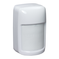
Hall Effect Door Switches (HEDS IV)
Hall effect door switches
HEDS IV
are intelli
ent contact
sensors that are mounted on doors. If the door is opened
when the area is armed, a si
nal is sent to the I9000 and then
to the EBI. Each CU supports a maximum of 31 HEDS IV on
each COM, for a total of 62. These totals include all device
t
pes shown in Fi
. 2. Fi
. 6 shows the wirin
connections for
HEDS IV.
Fig. 6. HEDS IV wiring connections.
NOTE: TB1-1 is
round for the s
stem.
QTY DEVICE DESCRIPTION UNIT POWER TOTAL POWER
CU
CC2 MAXIMUM OF 4 (NO BACKLIGHTING)
KID (MAXIMUM OF 8)
HEDS IV
BIC-2 OR BIC-2 HU (1 INPUT AND 1 LOGICAL OUTPUT)
BIC-2 OR BIC-2 HU (1 INPUT AND 1 OPTIONAL RELAY OUTPUT)
BIC-6 (6 PROGRAMMABLE INPUTS AND OUTPUTS)
MOM (MAXIMUM OF 8 PROGRAMMABLE LOGIC OUTPUTS)
RRI (REQUIRED FOR EBI RS-485 MULTI-DROP WIRING CONFIGURATIONS)
(45)
(10)
CC2 MAXIMUM OF 4 (WITH BACKLIGHTING)
(98)
(20)
(8)
(6)
(10)
(45)
(85)
M16259B
TOTAL POWER REQUIREMENTS FOR THIS INSTALLATION A
B
C = B - A
D
C + D
POWER AVAILABLE FROM PANEL (ISP = 800 mA)
SUBTOTAL (SHOULD BE POSITIVE +) IF NOT, ADD POWER AT "D"
IF TOTAL "C" IS NEGATIVE, ADD POWER SUPPLY (RIPS) (ISP = 800 mA)
TOTAL
(25)
1
1
EACH ISP HAS TWO POWER OUTPUTS (AUX 1 AND AUX 2). THE LOAD CONNECTED TO ONE ISP OUTPUT MUST NOT EXCEED 400mA.
2
2
2
COMBINATION OF CC2s WITH BACKLIGHTING AND CC2s WITHOUT BACKLIGHTING-FOUR TOTAL MAXIMUM.
M16105B
S1
U4
U5
U6
U1
DS1
C6
C7
U2
43 2
1
TB1
TB1-1 = COMMON
TB1-2 = +12V
TB1-3 = RxTx -
TB1-4 = RxTx +
WIRE CONNECTIONS
MOUNTING
HOLES (2)
CU COM
+ –
+ –
12 VDC
RS-485
 Loading...