Connections Installation
15BACNET-GW-3 Installation and Operation Manual – P/N LS10014-000NF-E:C6 5/5/2017
2.3 Connections
2.3.1 Connecting the BACNET-GW-3
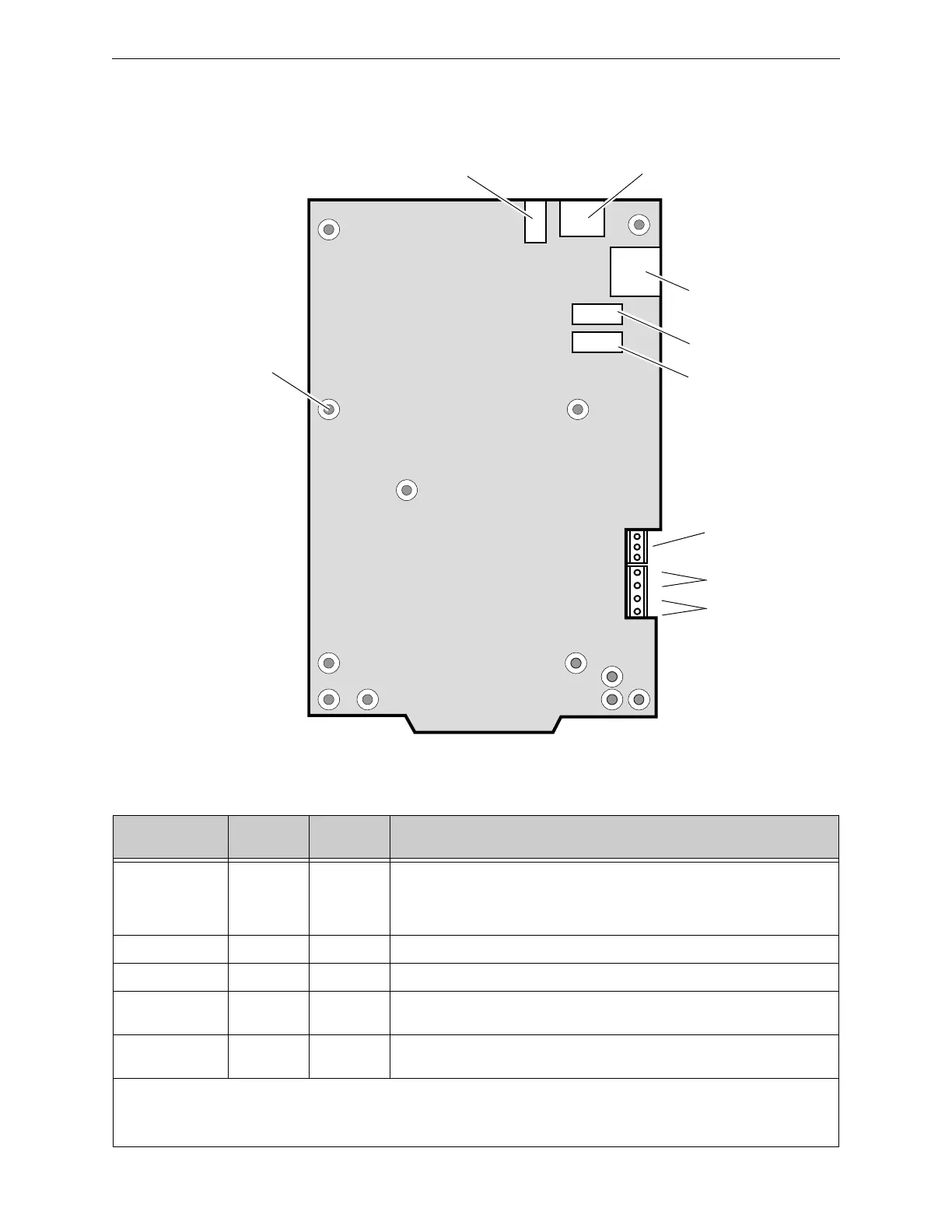
Figure 2.5 BACNET-GW-3 Connections
NUP A
Connector (J4)
USB “B” Device (J1)USB “A” Host (J2)
Not Used (J5)
Not Used (TB1)
Mounting Hole
(1 of 12)
-
24 V Out
24 V In
+
-
+
Ethernet
Connector (J3)
(TB2)
Table 2.1 Connection Specifications
Reference
Designator
Description
Circuit
Class
Specifications
TB2 DC Power 2 Power Source - FACP or UL 1481 listed 24 VDC regulated power supply
Nominal Voltage: 24 VDC, Regulated
Current: 125 mA
Locate in same cabinet or use close nipple fitting
J1 USB B 2 Locate in same cabinet or use close nipple fitting
J2 USB A 2 Locate in same cabinet or use close nipple fitting
J3 Ethernet 2 Line Impedance 100 ohm
Max Distance 328.083 ft. (100 m)
J4 NUP A 2 RS-232
Locate in same cabinet or use close nipple fitting
• All wiring from the power supply is power limited, and a separation of at least 1/4-inch (6.35 mm) must be maintained between
power limited and non-power limited wiring.
• All interconnects are power limited.
• Ethernet connections are power limited and supervised except for ground faults.
 Loading...


