ID3000 Series Installation & Commissioning Manual
Installation - Panel Electronics
21
997-274-000-6, Issue 6
September 2009
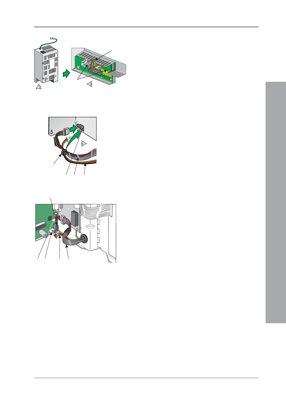
5.2.1.1 Main Chassis Wiring Connections
3 Connect the 10-way ribbon cable (G) and the power
cable (H) to the PSU3A. The power cable connects
at two positions, as shown.
4 Ease the connectors of these cables and the ferrite
through the aperture (I) in the main chassis. Pull the
cables through, taking up any slack.
5 With a sufficient length of each cable pulled through
to connect to the Base PCB, ease the grommet (J) in
to the aperture (I) and then slide it and the cables
sideways into the circular part until secure.
6 Terminate the cables on the Base PCB - the 10-way
ribbon cable (G) at socket SK8 (K) and the power
cable (H) at socket SK12 (L). Ensure the ferrite is
clear of all circuit boards.
Note: Connector (M) may not be fitted.
7 Fit the chassis into the back box (Section 5.4).
'A'
A
'B'
TEMP SNSR
+ -

 Loading...


