ID3000 Series Installation & Commissioning Manual
Installation - Panel Electronics
36997-274-000-6, Issue 6
September 2009
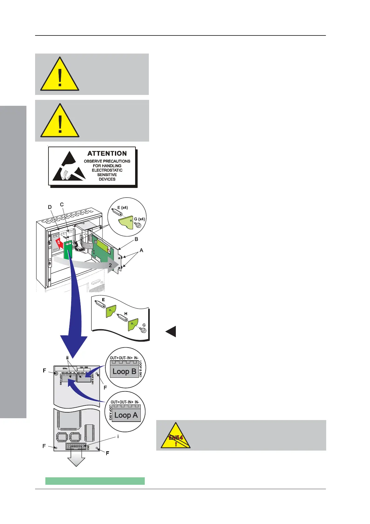
5.10 Enhanced Loop Interface PCB
The Enhanced Loop Interface PCB (PN: 124-292) provides
two additional fire detection device loops. The Enhanced Loop
Interface PCB is located within the main chassis PCB enclosure,
adjacent to the Base PCB. The PCB is secured in position using
four metal spacers and four Posi SEM screws, which are
provided in the Enhanced Loop Interface PCB kit (PN: 020-549).
To fit the Enhanced Loop Interface PCB follow the
instructions below.
Before starting, make sure you have a PC back-up of
the panel’s current configuration data.
Ensure you take appropriate anti-static precautions
before undertaking this procedure.
With the front cover moulding(s) removed (see Section 2.7)
and ALL power disconnected, proceed as follows:
1 Using a suitable-sized coin, release the two quarter-turn
fasteners (A) located at the left-hand side of the main chassis
front door (B). Open the door to gain access to the main
chassis’ PCB enclosure (C) containing the Base PCB (D).
2 If the location at which the Enhanced Loop Interface
PCB is to be fitted is obstructed by a 3rd-layer PCB
(future development), remove the PCB to gain access
to the mounting location.
3 Fit the four supplied hexagonal metal spacers (E) to the
Base PCB as follows: Insert one spacer in each of the two
holes either side and above socket connector SK4, SK6 or
SK7 (use left-most vacant position), then fit the remaining
spacers in each of the two holes directly above these spacers.
Tighten down fully using a 5.5mm Hex socket tool.
4 Observing anti-static precautions, remove the Enhanced
Loop Interface PCB from its packaging. If, after
inspection, no damage has occurred in transit and with
it correctly orientated, position it so that its mounting holes
(F) are directly above the spacers. Secure the PCB to
these spacers using the M3 x 8mm SEM screws (G). If
a 3rd-layer PCB is to be fitted or refitted at this location,
do not fit the screws to the left-hand spacers, instead fit
the spacers (H) supplied with the 3rd-layer PCB and fit
the 3rd-layer PCB in accordance with its instructions.
5 Make all necessary wiring and cabling connections to
the Enhanced Loop Interface PCB - see details below.
6 If no other PCBs require fitting, close and secure the
main chassis front door, re-connect mains power and
the batteries and replace the front cover moulding(s).
7 To replace the Enhanced Loop Interface PCB, first
reverse the above procedure, steps 4 to 6, and then
fit the replacement Enhanced Loop Interface PCB
using steps 4 to 6.
To comply with the requirements of EN54, an Enhanced
LIB PCB must be replaced by another Enhanced LIB
PCB - refer to Section 11.2.2 Number of Loops on
Panel of the Panel Configuration Manual.
Make sure you have
a PC back-up of the
current
configuration data
With
3rd-layer PCB
Socket connector (see step 4)
WARNING -
Disconnect ALL power
from the ID3000 Series
panel
Enhanced Loop Interface PCB - Part Number 124-292
EN54-2: 13.7
Maximum of 512 Sensors and/or MCPs per
panel unless ELIBs are used.

 Loading...


