ID3000 Series Installation & Commissioning Manual
Commissioning
52997-274-000-6, Issue 6
September 2009
7.8 Repeaters
Commission the repeaters as described in the repeater
manual.
7.9 Configuration and Handover
After all external wiring has been connected to the panel
and the status is ‘NORMAL’, the panel can be configured
for the particular system requirements. Information on
configuring the panel is given in the ID3000 Series Panel
Configuration Manual (ref. 997-506-XXX).
After configuration has been completed and any faults
revealed have been rectified, the system will be ready
for commissioning tests, as required by the appropriate
standards, prior to handover to the user.
7.10 System Test
On completion of all commissioning procedures
described in this section, you must now perform:
a. Zone walk tests
b. Control output tests
7.10.1 Zone Walk Test
Refer to the ID3000 Series Operating Manual (ref. 997-
505-XXX) Section 6.2, Zone Walk Test for further
details.
7.10.2 Control Output Test
Refer to the ID3000 Series Panel Configuration Manual
(ref. 997-506-XXX) Section 12.1, Control Output Test
for further details.
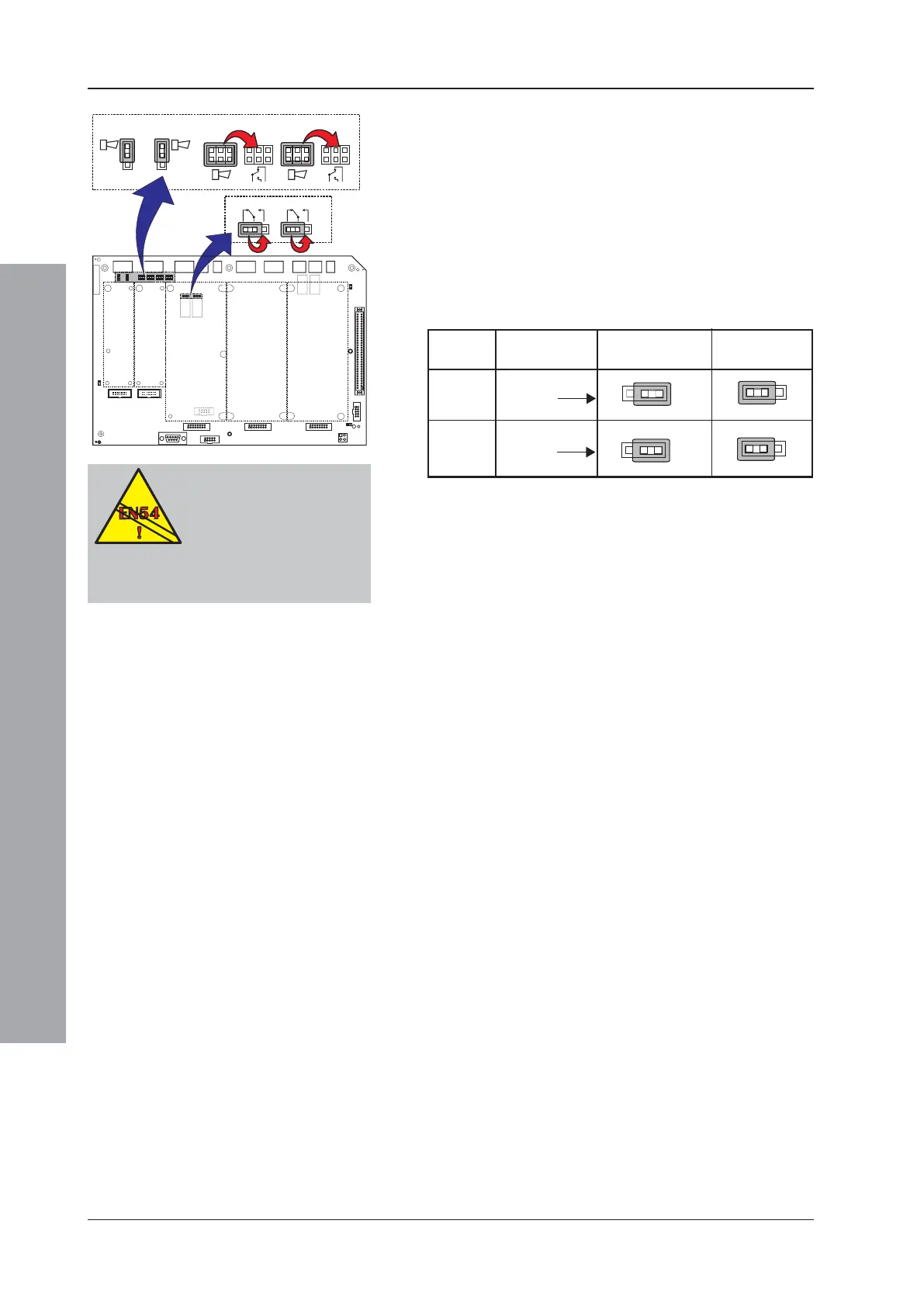
7.7 Volt-free Contact Output Option
Two ID3000 Series control panel sounder circuits, i.e.
sounder circuits 3 and 4, can be configured to provide a
volt-free, normally-open or normally-closed contact.
For either sounder circuit, the configuration changes are
carried out on the Base PCB simply by moving up to two
jumper links. The link setting instructions are defined in
the table below. These changes must only be made with
the system powered down. The changes become
effective automatically on power-up.
S / No.
UE
UE
OUT 1
OUT 2
OUT 3
OUT 3
OUT 4
OUT 4
VFC
VFC
EN54-2 : 8.2.5a/b/8.2.4f.
Outputs configured as volt-
free contact are not
monitored, so are not
suitable for use to activate
fire alarm devices such as sounders, fire
alarm routing equipment, or fire alarm
protection equipment.
Output
Fit Jumper
Links over:
For Normally
Open
For Normally
Closed
3
4
JP5
JP8
JP8
JP9
JP8
JP9
JP7
JP9

 Loading...


