ID3000 Series Installation & Commissioning Manual
Installation - Panel Electronics
31 997-274-000-6, Issue 6
September 2009
5.6 Display PCB
The Display PCB is located on the inner face of the main
chassis door. In the unlikely event that the Display PCB
becomes faulty and needs to be replaced, the front door
assembly, supplied as part of a kit (PN: 020-571-XXX)
needs to be replaced.
The manufacturer strongly recommends that BEFORE
attempting this procedure, and after isolation of the mains
supply and disconnection of the batteries, that you
remove the batteries from the back box until the panel is
ready for re-application of power.
To replace the main chassis door, the front cover
moulding(s) must be removed by releasing the M6
socket-headed screws using a 4mm hexagonal socket
key (or the special Notifier security tool, if applicable).
Before starting, make sure you have a PC back-up of
the panel’s current configuration data.
Ensure you take appropriate anti-static precautions
before undertaking this procedure.
With ALL power disconnected, follow the instructions below:
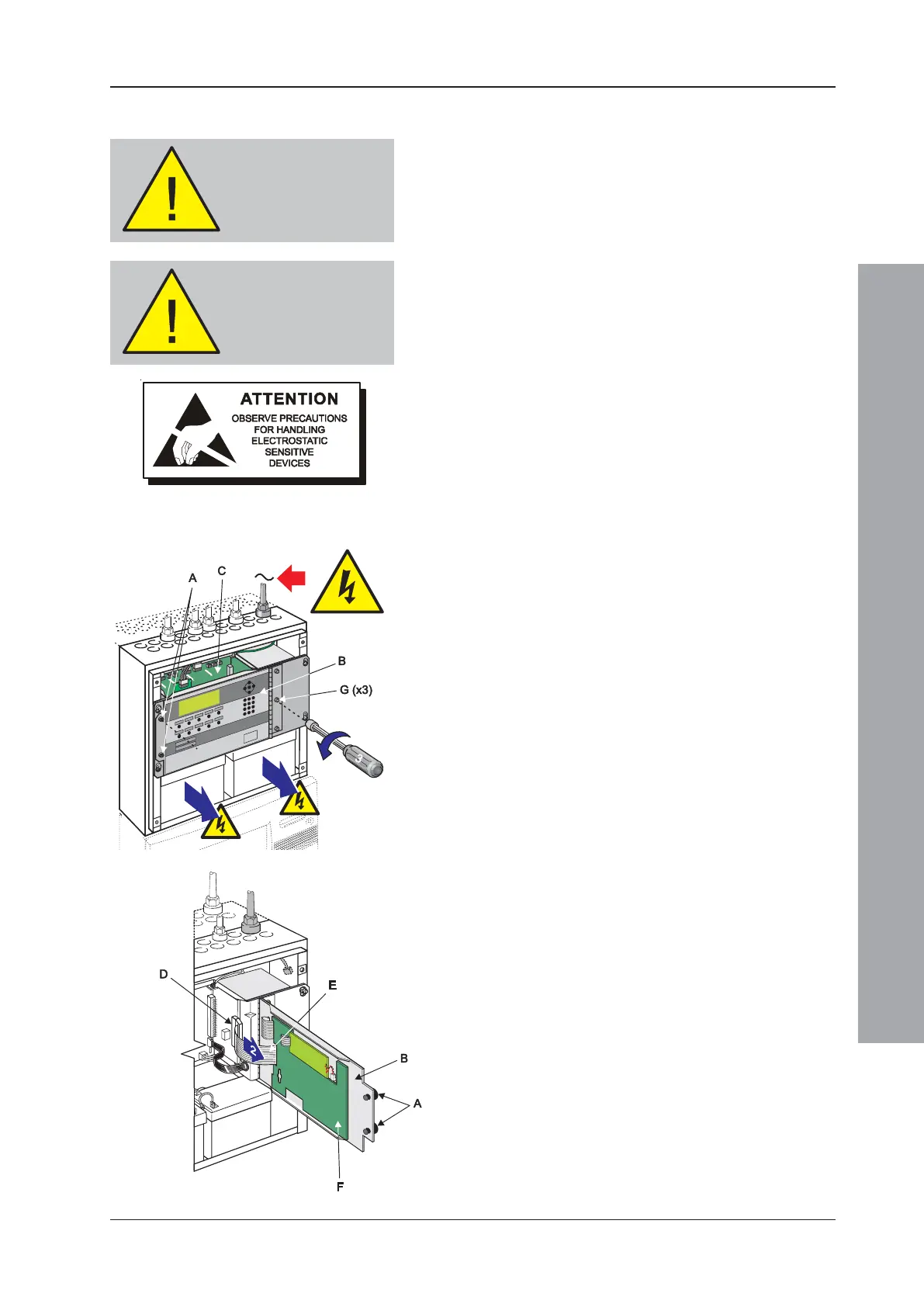
1 Using a suitable-sized coin, release the quarter-turn
fasteners (A) located at the left-hand side of the main
chassis front door (B). Open the door to gain access
to the main chassis’ PCB enclosure (C).
2 At connector J2 (D) on the Processor PCB, disconnect
the 34-way ribbon cable (E) from the Display PCB (F).
Close the main chassis front door and secure using
the two fasteners.
3 Holding the top edge of the door, use a nutdriver to
loosen the three M4 x 6 hexagonal-headed screws (G)
located down the right-hand side of the main chassis
door. Remove the centre and lower screws and with
only the top screw securing the right-hand side of the
door, release the two quarter-turn fasteners and support
the door while you remove the last screw.
4 Remove the door assembly and store safely in an
anti-static bag.
5 With the replacement door assembly correctly orientated
- as shown at left - offer it to the main chassis. Support
the door while inserting one of the three screws removed
in step 3. Tighten it by hand and then close the door and
secure. Insert the remaining two screws and, using a
nutdriver, fully tighten all three screws until secure.
6 Re-open the door and re-connect the 34-way ribbon
cable disconnected in step 2.
7 Re-fit the batteries.
8 Re-connect mains power and the batteries.
9 Close the door and secure using the two quarter-turn
fasteners.
10 Replace the front cover(s) and secure.
Make sure you have
a PC back-up of the
current
configuration data
WARNING -
Disconnect power
from the ID3000 and
remove batteries

 Loading...


