100 RP-2001 Series Manual — P/N 52985:D5 1/26/2017
FACP Configuration Templates Template 2: Single Hazard - Cross-Zone With Manual Release
FACP Relay Operation
The following description of FACP relay operations are in addition to normal system operation.
• Alarm Relay - activation of Input Zone 1 (2-Wire Smoke) or Zone 2 (Fire) or Zone 3 (Water-
flow - with Waterflow Delay time) or Zone 4 (Manual Release) or Zone 5 (Pull Station) will
operate Alarm Relay
• Trouble Relay - any system trouble will activate the Trouble Relay
• Supervisory - activation of Zone 6 (Supervisory) will operate the Supervisory Relay
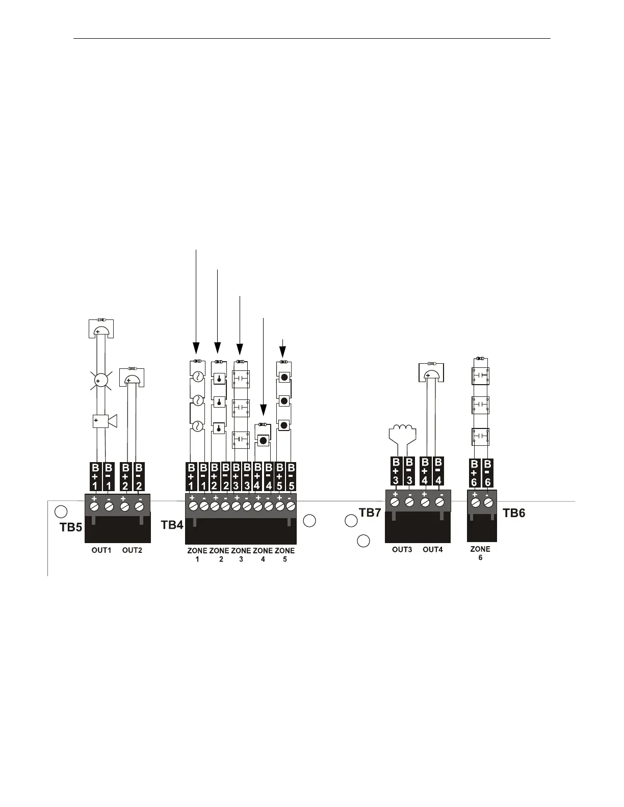
Device Installation Example for Template 2
Notes:
1. Waterflow Delay is programmed for 60 seconds.
2. All End-of-Line Resistors, illustrated in this example, are 4.7KΩ, ˝ watt (PN: 71252).
3. All devices are connected as Class B circuits. For details on connecting as Class A circuits,
refer to “N-CAC-5X Class A Converter Module” on page 29.
Output Circuit #1
Alarm NAC
Output Circuit #2
Waterflow NAC
1
Input Circuit #1
2-Wire Smoke
Input Circuit #2
Fire (Heats)
Input Circuit #3
Waterflow
1
Input Circuit #4
Manual Release
Input Circuit #5
Pull Station
Output
Circuit #3
Release
Solenoid 1
Output Circuit #4
Supervisory Bell
NAC
Input Circuit #6
Supervisory
deluge temp8.cdr

 Loading...


