PRIMUSr 1000 Integrated Avionics System
A28--1146--112--00
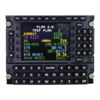
Electronic Flight Instrument System (EFIS)
4-94
D Bus Voltage and Amperage Loads -- A generator volts andamps
display is normally shown in green for the following dc power
sources:
- Generators 1 through 4 (GEN 1/2/3/4)
- Auxiliary power unit (APU) and ground power unit (GPU)
D DCPowerInterconnectBuses--Thedcpowerinterconnectbuses
are normally displayed in green. The resolution of the voltage
display is 0.1 vdc. The resolution of amperage readouts is 5 amps.
NOTES: 1. When a digital value exceeds the limit, the value turns
amber, is boxed and flashes for 5 seconds.
Depending on the circumstances, this annunciation
changes if there has already been an abnormal
situation.
2. The annunciation of power sources exceedances
only occurs when an electrical power system
message is displayed on the CAS.
3. Failureofaninterconnectbusisindicatedbyasolid
amber line.
4. The GPU power display does not include an
amperage load indication.
5. APU data is displayed under the following
circumstances:
- APU master is ON
- APU turbine speed is greater than 10%
6. GPUdataisonlydisplayedwithweight--on--wheels
(WOW).
D Battery Voltages and Operating Temperatures -- Battery
voltages andoperating temperatures in °C are displayedin a digital
format. Normal indications are displayed in green.
NOTES: 1. Amber (abnormal) annunciations occur when an
electrical power system message is displayed on
CAS.
2. Thedisplayedbatterytemperatureisonlytransmitted
from the primary sensor. The battery temperature
CAS message can betriggeredby either theprimary
or secondary battery sensor.
3. Valid/invalid indications for the battery display are
only transmitted from the primary sensor.
 Loading...