PRIMUSr 1000 Integrated Avionics System
A28--1146--112--00
2-9
System Description
FLIGHT MANAGEMENT SYSTEM (FMS) (OPTION)
The single FMS consists of the following:
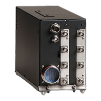
D Flight Management Computer
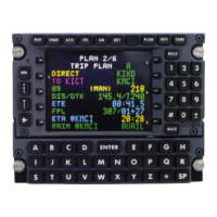
D Control Display Unit (CDU)
D Data Loader (DL).
The FMS displays lateralandverticalnavigation guidanceparameters,
and is coupled laterally to the FGS. The CDU displays selected flight
plandata.Thealphanumerickeyboardistheinterfacebetweenthepilot
and the system.
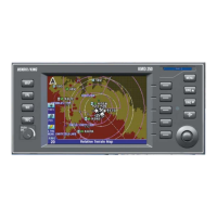
The FMS uses five long--range sensors that are connected through
ARINC 429 buses. The FMS is also connected to the dual PRIMUS
â
II Radio System’s VOR/DME receivers.
The FMS interfaces to the MADC, EFIS, and FMS. FMS pilot interface
is done with the cockpit mounted CDU. VOR/DME and global
positioning system (GPS) are the sensor inputs. Under normal
conditions, FMS position is always based on the GPS inputs.
The FMS is the source of map data for the MFD. Map displays are
generatedfromanFMSnavigationdatabase.The navigationdatabase
is normally updated every 28 days. Thedataloaderisusedto loadpilot
defined flight plans, waypoint data, and aircraft performance data.
OTHER SWITCHES AND CONTROLS
D AP (Autopilot) DisconnectSwitch --The AP disconnect switch is
mounted on the control wheel. When pushed, it disconnects the
autopilot and yaw damper.
D TCS (Touch Control Steering) Button -- The TCS button is
mounted on the control wheel. When pushed, the pilot can change
aircraft attitude, altitude, airspeed, and/or vertical speed, without
permanently disengaging the autopilot.
D GA(Go--Around)Button--TheGAbuttonislocatedonthethrottle.
Under normal conditions, if the AP is engaged, it remains engaged
and the automatic flightcontrolsystem(AFCS) commands coupled
go--around minimum speed hold function for the command bars. If
only the flight director is available, a fixed pitch angle of 12° is
commanded.
D External AHRS Switches -- Refer to Appendix A, Attitude and
Heading Reference System (AHRS), for a description of the
magnetic/ directional gyro (MAG/DG) and DG CW/CCW switches.
 Loading...