16 www.honeywell.com
PW-6000 Installation
Setting Up the PW-6000 Hardware
3.4.2 Run TimeSupplying Power to the PW-6000 Interface
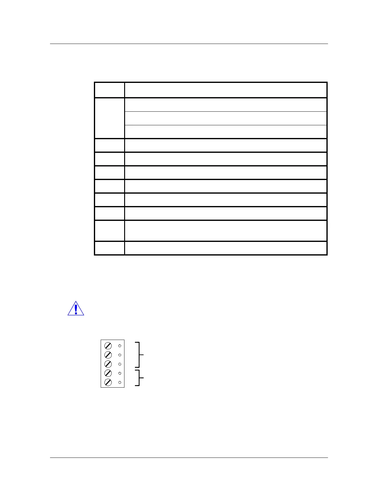
3.5 Supplying Power to the PW-6000 Interface
The processor accepts 12Vdc for power. Locate power source as close to the unit as
possible and connect it with minimum of 18AWG wires.
Caution: Observe POLARITY on 12 VDC.
ATTENTION: Observez la polarité du 12 VCC
Figure 2: PW-6000 Power Terminals
Table 5 PW-6000 Status LED Combinations During Run Time
LED
Description
1 Off-Line / On-Line and Battery Status
Off-Line = 20% On, ON-Line = 80% On
Double Flash means the Battery is Low
2 Primary Host Communication Activity (Ethernet or Port 1)
3 Port 2 Communication Activity
4 Port 3 Communication Activity
5 ON = Writing to Flash Memory. Do NOT cut off power when this LED is ON.
6TBD
SPD On-Board Ethernet Speed. OFF = 10MBS. ON = 100MBS.
ACT OFF = No On-Board Ethernet Activity. ON = On-Board Ethernet Activity
(YELLOW LED).
LNK OFF = ON Link. ON = Good Link (GREEN LED).
PORT 3
+12V
GND
-
+
TB1
GND
TR-
TR+
12Vdc ±10%
 Loading...