Honeywell
14
73024521a © Elster GmbH | All rights reserved. Subject to modification
2. Structure and function
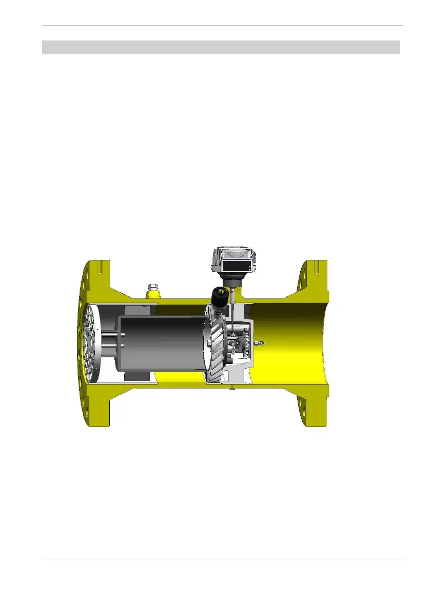
Operating principle
The gas flowing into the meter causes the turbine wheel to turn, with the
number of revolutions being proportional to the operating volume passing
through the meter. The gas flowing into the meter is accelerated by the
specially designed flow conditioner which is located at the meter inlet. This
flow conditioner is designed to ensure that any influences on the flow, such
as swirls or asymmetric flow, are eliminated. This ensures high measurement
accuracy even for low flow rates within the permissible error limits.
The speed of the rotating turbine wheel is reduced by a gear assembly. A
transmission shaft connected to this gear assembly drives the 8-digit
mechanical roller index in the unpressurized index head via a magnetic
coupling. Having passed the turbine wheel, the gas leaves the meter through
a flow-optimized outlet duct which is designed to allow maximum pressure
recovery.

 Loading...


