Honeywell
73024521a
© Elster GmbH | All rights reserved. Subject to modification
21
English
3.5 Installation position and flow direction
Install the meter ideally in a horizontal position with the index at the top.
The permitted installation/operating positions of the meter are specified
on the main plate in accordance with the designations “H”, “V” or “H/V”
(H = horizontal, V = vertical) to DIN EN 12261. If you have specified the
installation or operating position when ordering, all attachments will have
been fitted in accordance with the installation position ex-works.
The minimum length of the inlet section for SM-RI-X must be at least
twice the nominal diameter (2 x DN) for reasons relating to measurement
accuracy.
The inlet section must be designed as a straight pipe section with the
same nominal diameter as the meter.
The length of the outlet section is at least 1 x DN of the same nominal
diameter.
The direction of flow is indicated by an arrow on the housing:
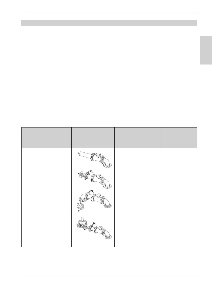
Flow disturbances
sections
Pipe sections installed at a
distance of 2D upstream
of the meter inlet
SM-RI-X
Q75
Minor disturbances
- single manifolds
- twin manifolds
- diffusers
L ≥ 2D
No flow conditioner
L ≥ 5D
Major disturbances
- pressure regulators
for gas
- other restrictors
L ≥ 2D
No flow conditioner
L ≥ 5D
Flow
conditioner
recommended
Table 4 | Inlet sections

 Loading...


