OPERATOR MANUAL // SECTION 2: INSTALLATION
HONEYWELL 15
Make sure the Panel's power supply can withstand the load current of the
total number of Detectors connected to it. For example, if 10 (ten) Model
SS4-A/-A2 Detectors are connected to a single Panel's power supply
(multiplying 75 mA by 10), the power supply must be able to withstand at
least 750 mA + 10% (0.75 A + 10%). This load current must also be taken
in consideration for calculating the Panel's 24-hour power backup
requirements.
2.2 Installation Procedure
2.2.1 Configuring and Wiring Detectors
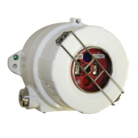
To configure and wire a Model SS4-A/-A2 Detector, or to replace the
Detector module, the module must be removed from the enclosure. After
the configuration settings and wiring connections have been completed,
the module should soon be re-installed in the enclosure to avoid
contamination from the environment.
NOTE: Avoid touching the Detector sensors at the front of the
Detector module. If touched accidentally, they should be cleaned per
instructions of Section 3.2.
2.2.2 Removing Detector From Its Enclosure.
a. With electrical power off (verify that electrical power is off by
making sure that the Detector's LEDs do not blink for at least 15
seconds), loosen the Allen-head screw at the base of the metal
enclosure top lens cover.
b. Remove the cover and set it aside along with the "O" ring avoiding
contamination.
c. Loosen the three Philips head captive screws located on the top
circuit board.
d. Carefully lift out the module, sliding it along the three metal
standoffs.
2.2.3 Configuring the Detector Module.
Set the DIP switches located on the center PC board of the Detector
module to desired settings. Refer to Section 1.5 and Table 2 for DIP
switch settings.
 Loading...