OPERATOR MANUAL // SECTION 2: INSTALLATION
HONEYWELL 17
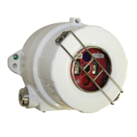
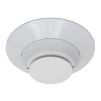
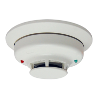
2.2.5 Wiring the SS4-A/-A2 Detector for 4 or 20 mA Current Mode Operation (Optional)
For applications requiring a 4-20 mA analog output, order the Detector with
the Optional 4-20 mA Module Assembly, P/N MA420-4. The module
must
be Factory installed and certified along with the Detector.
The following analog output levels are available from the Detector
equipped with the MA420-4 Module. The module is capable of driving a
maximum load impedance of 283 Ohms:
NORMAL Operation 4 +/- 0.6 mA
ALARM 20 +/- 0.6 mA
FAULT < 0.6 mA
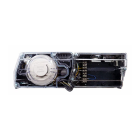
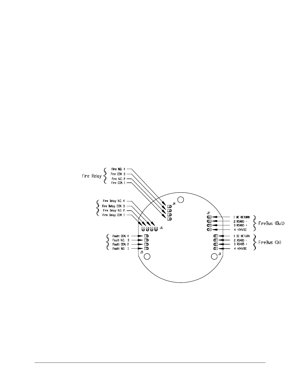
To use the analog output of an SS4-A/-A2, make the following connections:
24 V DC J2, pin-4
24 V DC RTN J2, pin-1
4-20 mA output J5, pin-4 (+)
4-20 mA RTN J1, pin-1 (-)
The fire Alarm and fault relays of a Detector equipped with the MA420-4
Module are not usable. However the Detector’s Verify Relay may still be
used as a separate Fire Alarm output. Refer to Table 2: “Configuration DIP
Switch Settings” to set DIP switches properly.
NOTE: J1 is a "loop through" connection to J2. The +24 V supply is
connected to J2 pin 4. The red lead connection of the MA420-4 must stay
in J1, pin-4. Also, the 8.66 K Ohm supervising resistor must remain
connected at the Fire Alarm relay contacts J4 pin-4 to J4 pin-1, or a Fault
condition will occur.
 Loading...