OPERATOR MANUAL // SECTION 2: INSTALLATION
HONEYWELL 14
SECTION 2: INSTALLATION
2.1 Installation Instructions
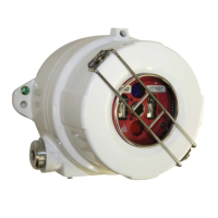
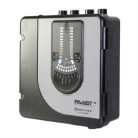
This section describes the installation of the Model SS4-A/-A2 Detector for
the Stand-Alone relay mode. It is recommended that junction boxes be
used to wire the Detectors. Determine the configuration settings for the
device(s) and the number of connections to be used (Fire, Fire Verify,
Fault, and Power) depending on the desired Detection Range and the Fire
Control Panel type used (refer to the Fire Control Panel Manual for details).
2.1.1 Installation Precautions
The following precautions should be observed during installation of Model
SS4-A/-A2 Detectors.
1. Make sure that the external electrical power is turned
OFF before
connecting the Detector.
2. Printed circuit board components of the Detector are susceptible to
damage from electrostatic discharge. Do not handle the
Detector's module (and its printed circuit boards) without
adequate grounding and observing all necessary measures to
prevent the effect of electrostatic discharge (ESD).
2.1.2 Conduit Installation
When planning the conduit, follow these recommendations.
1. If only one of the two 3/4 inch NPT conduit openings on the Model
SS4-A/-A2 Detector enclosure is used, seal the unused opening
with a threaded plug and approved sealing material.
2. In areas where moisture may accumulate, install an approved
conduit trap or drain.
3. A seal should be installed 6” from the enclosure wall for all
applications requiring a Class I, Div. 1 Explosion-Proof rating.
2.1.3 Wiring Recommendations
To prevent intermittent connections, Honeywell Analytics recommends
using junction boxes. Install a junction box near each Detector location.
Wire each Detector to its junction box. Use screw-down terminal strips
inside the junction box to make the connections from the Detector's
terminals to an FM Approved or UL listed Fire Alarm Panel. Also use
FM/UL Approved junction boxes and terminal strips.
NOTE: Avoid wire splices. However, if wire splices are necessary, all
splices should be soldered. Utilization of good wiring practices will
simplify installation, improve reliability, and facilitate maintenance.
2.1.4 Power Supply Considerations
The Model SS4-A/-A2 Detector uses 24 Volts DC at a maximum current of
75 mA (with the 4-20 mA option the maximum supply current is 95 mA).

 Loading...
