OPERATOR MANUAL // SECTION 4: DETECTOR CONNECTIONS & SWITCH
OPTIONS
HONEYWELL 26
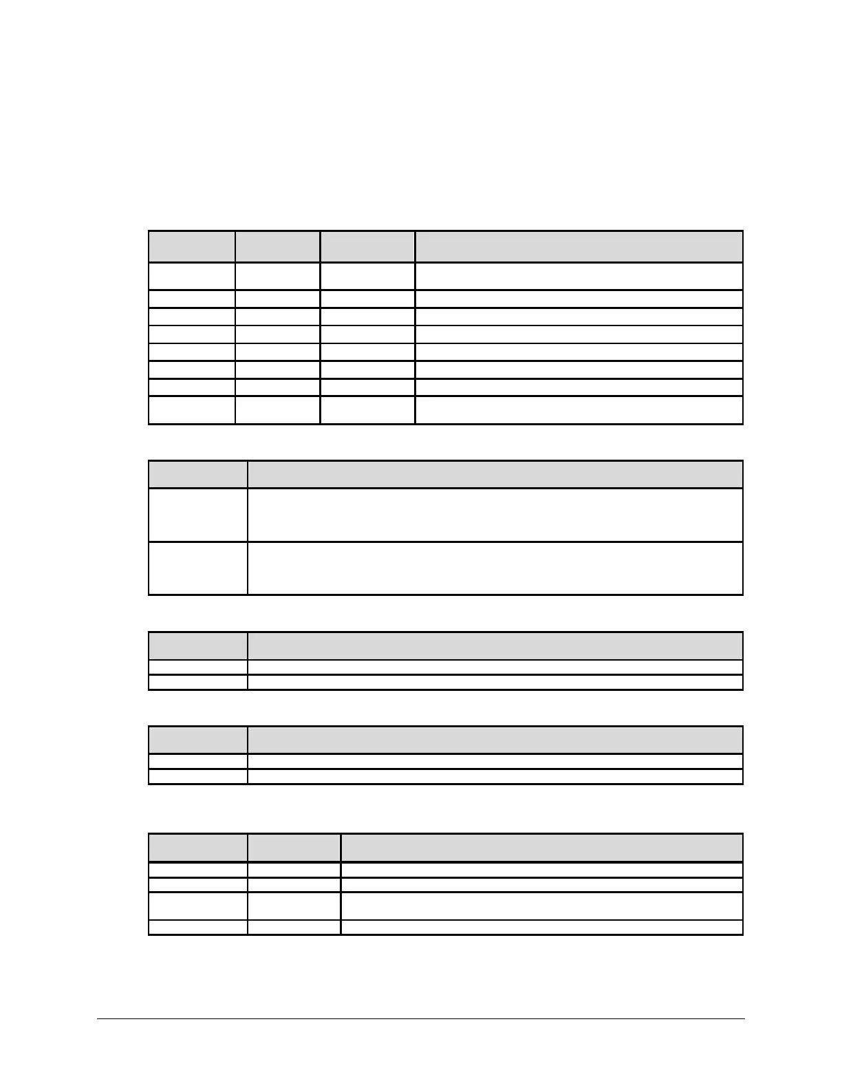
4.2 Detector Switch Options
TABLE 2: Configuration DIP Switch Settings
Verification Time
DIP SWITCH
DIP SWITCH
DIP SWITCH
Verify is disabled and the Verify Relay is unused. Factory setting
Verify is enabled and the Verify time is 5 seconds.
Verify is enabled and the Verify time is 10 seconds.
Verify is enabled and the Verify time is 15 seconds.
Verify is enabled and the Verify time is 20 seconds.
Verify is enabled and the Verify time is 25 seconds.
Verify is enabled and the Verify time is 30 seconds.
open open open
Verify is disabled and the Verify Relay operates as a second Fire
Relay.
Latching
DIP SWITCH
DESCRIPTION
open
-Latching mode. If Verify is enabled then the Verify Relay will de-energize approximately 10
seconds after it energizes. If Verify is disabled then the Fire Relay(s) will de
-
energize approximately
10 seconds after it energizes. The SS4-A2 Factory setting is Non-Latching
closed
Latching mode. If Verify is enabled then when
the Verify Relay energizes it will remain energized
until the Detector is reset. If Verify is disabled then when the Fire Relay energizes it will remain
energized until the Detector is reset. The SS4-A Factory setting is latching
IR-Only Enable
DIP SWITCH
Fire Alarm declaration UV and IR energy. Factory setting
A Fire Alarm may be declared without UV being detected.
Test Cycle
DIP SWITCH
DESCRIPTION
Testing of the Lens occurs every 30 minutes. Factory setting
*Testing of the Lens occurs every 6 minutes
* Utilization of the 6-minute period may adversely affect the source tube service life.
Fire Range
DIP SWITCH
DIP SWITCH
DESCRIPTION
Set to detect an industry standard 1 sq. ft. fire at 15 ft. on axis.
Set to detect an industry standard 1 sq. ft. fire at 30 ft. on axis.
Set to detect an industry standard 1 sq. ft. fire at 45 ft. on axis. Factory setting
Set to detect an industry standard 1 sq. ft. fire at 60 ft. on axis.
 Loading...