OPERATOR MANUAL // SECTION 2: INSTALLATION
HONEYWELL 18
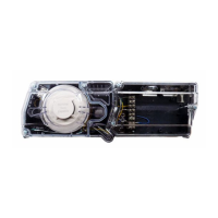
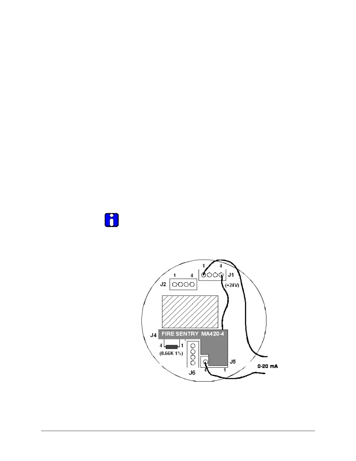
Figure 3: SS4 Detector Module with MA420-4 Installed
(Rear View)
2.2.6 Wiring the Detector Relays
a. Insert relay cables into the Detector enclosure base through one of
the conduit openings. Refer to Figure 6.
b. Fire Alarm Relay - Connect wires for Fire Alarm to the appropriate
J4 terminals of the Detector. For Normally Open relay contacts,
install wires into pins 3 and 4 and firmly tighten down the slotted
screws with a small screwdriver. The Fire Alarm relay is de-
energized during normal operation and will energize when detecting
a fire.
c. Fault Relay – Connect wires for Fault to the appropriate terminals
of the J5 connector. For Normally Closed relay contacts, install
wires into pins 3 and 4 and firmly tighten down the slotted screws
with a small screwdriver. The fault relay is energized during normal
operation and with no fault detected, as shown in Figure 2. The
fault relay will de-energize when a fault is detected.
 Loading...