OPERATOR MANUAL // SECTION 1: TECHNICAL DESCRIPTION
HONEYWELL 8
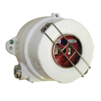
1.1.2 Applications
Applications of the Model SS4-A/-A2 Detectors include warehouses,
aircraft hangars, petrochemical facilities, Silane gas storage, Gas turbines,
and Power plants, among others.
1.1.3 Detector Locations
For unobstructed performance, considering Detector locations in
application areas, avoid sources, other than fire, which may cause false
alarms, such as operations utilizing welding or gas torch equipment, high
power sources of EMI or RFI, or artificial lighting pointed directly at the
Detector. Locations experiencing strong mechanical or acoustical
vibrations should also be avoided. For optimum performance, locate the
Detector(s) as close as possible to the potential fire source, preferably,
along the axis of the vision cone. Install enough Detectors to completely
eclipse the fire hazardous area. Assure accessibility for the Detector lens
cleaning, as well as best possible protection and/or cleaning from fog, rain,
ice, dust, hazardous atmospheres, and other adverse elements. If
necessary, utilize the Steel Swivel Mount (Model SM2) or 316 Stainless
Steel Swivel Mount (Model SM4) for greater flexibility in mounting locations
(See Figures 4 and 5).
1.2 Stand-Alone Operation
For Stand-Alone operation, the Model SS4-A/-A2 Detector may be
connected to a FM Approved or UL listed Fire/Security Panel. The Detector
operated in the Stand-Alone mode uses the Fire, Fault, and Verify
(optional) relays to interface to the Fire/Security Panels. For Stand-Alone
operation, the Detector’s Fault relay is automatically configured by the on-
board microprocessor. The input current of the Model SS4-A/-A2 Detector
is about 15 mA higher in the Stand-Alone mode compared to FS2000
System operation.
NOTE: The Fault relay is not available when the Detector is
wired to the FS2000 System.
1.3 FS2000 System Operation
For FS2000 System operation, the Detector Fire and Fault signals are sent
digitally to the FS2000 System Controller using the four wire FS2000
FireBus. The FireBus provides the 24 Volt DC power for the Detector and
RS-485 digital communication (Refer to Honeywell Analytics document
MN0003 entitled "FS2000 FIRE EARLY WARNING SYSTEM -
INSTALLATION and OPERATIONS GUIDE"). For special remote alarm
applications, users may also connect directly to the Detector’s Fire alarm
relay.
NOTE: When the Model SS4-A/-A2 Detector is connected to the
FS2000 System using FireBus communication, the Controller
automatically disables the Detector’s Fault relay.
 Loading...