Daily Operation
MAN0996_Iss 1_02/16 Touchpoint Plus
Pt. No. 3011M5044_EN 21 User Guide
Chapter 4. Touchpoint Plus User Guide
The TPPL Touchscreen is the primary control and viewing method but there is also an optional Web Interface that
currently allows remote viewing only (see Ch.4.17 Monitoring TPPL via the Optional Web Interface for more details).
4.1 User Interface General
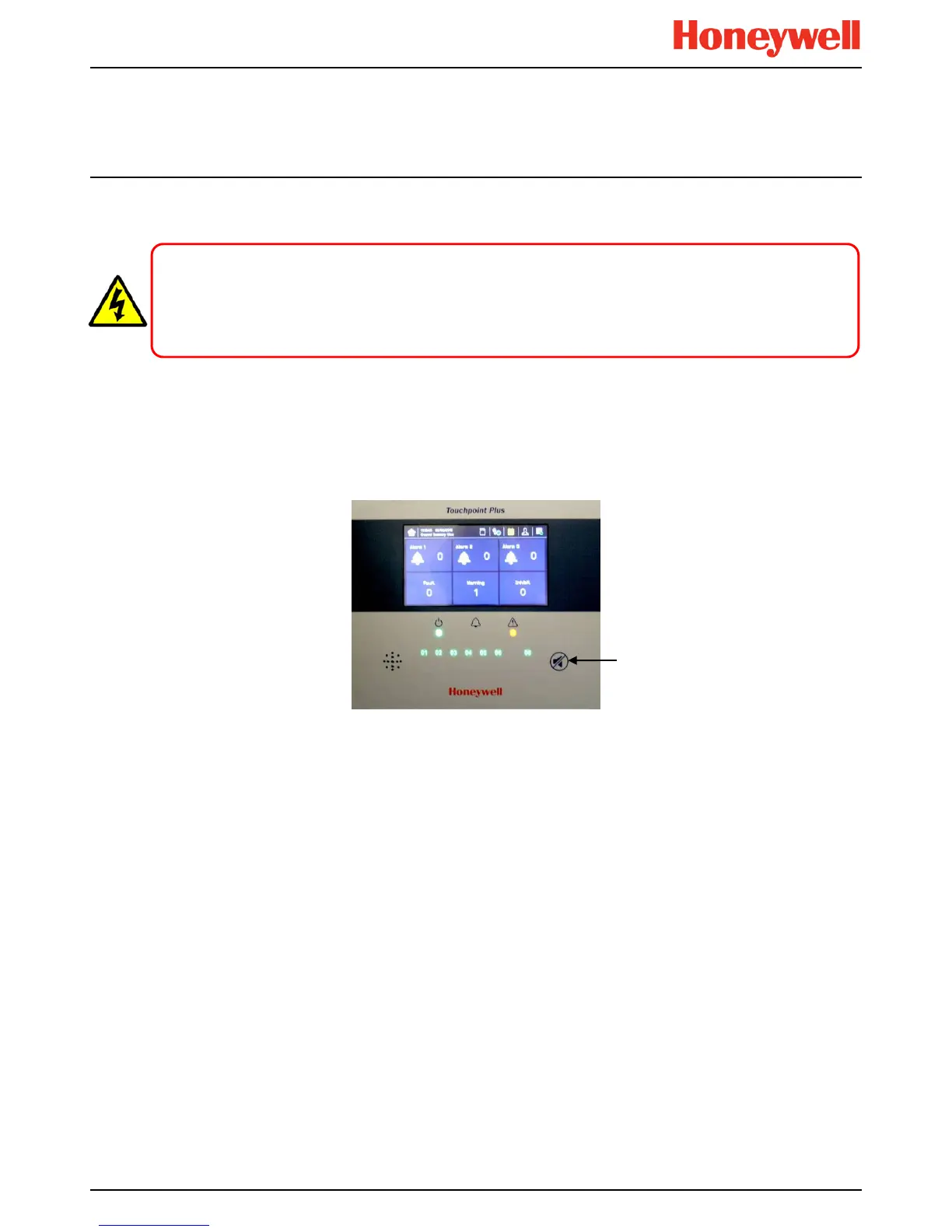
Figure 13. Touchpoint Plus Controller User Interface
The User Interface panel (shown above) has:
• A colour Touch screen for normal system operation, maintenance and configuration
• Power, Alarm / Fault and Inhibit state LEDs
• Active Channel (01 to 08) status indicators (Ch. 07 is not commissioned in this example)
• Active Expansion Channel (09 to 16) status indicators (not commissioned above)
• Accept* / Reset membrane button (arrowed above)
• Integral Alarm Buzzer (Left side)
*The membrane button acknowledges and silences active alarms and resets latched alarms, depending on the situation
and how long it is pressed. See Ch.4.8 Responding to Alarms for further information.
Further System Interfaces consist of:
• Remote inhibit and remote reset terminals in the Main module
• One fixed relay and two configurable relays in the Main Module for system Failure, Alarm and Inhibit
• Three dedicated alarm outputs for visual and audio alarms
• An SD Card slot for data logging and firmware/software updates
• An optional expansion unit with optional dual input module (mV & mA)
• Optional remote Web Interface networking via RS485 port
• Optional remote Modbus TCP/IP via hard-wired terminal
WARNING
Opening the enclosure may expose live electrical circuits. Touching exposed terminals or wires may cause death
or serious injury. Always turn off and isolate the system before opening the door. Do not switch back on until the
door is reclosed and secured. Do not operate TPPL with the door insecure.