Installation Instruction VARIODYN
®
D1 System
FB 798663.GB0 / 05.19 43
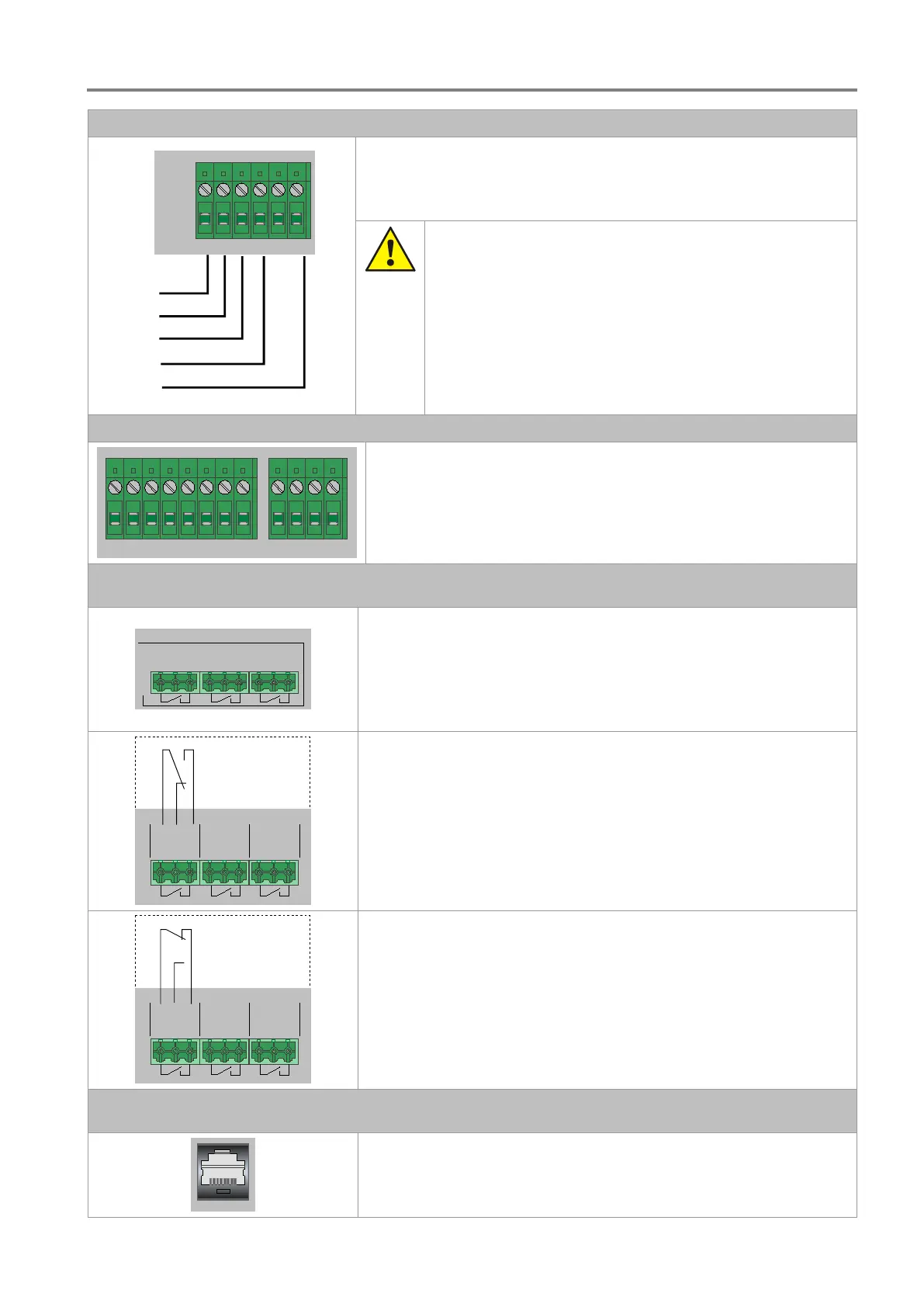
L1
N
PE
MAINS
max.
3 x 18A
L1
L2 L3
N
PE
L2
L3
Connection of the 230 V AC rated voltage L1 / L2 / L3 and N / PE.
Danger – Electric shock!
Assembly and installation work may only be performed when the
system is de-energised (voltage free).
ESD / EMC preventive measures
Before handling electronic modules, always take suitable
precautions to prevent static electricity.
The control panels must only be connected to the mains by
qualified electricians and in compliance with all relevant
standards and guidelines.
Up to 4 components can be connected to the three connection
terminals (phases). Each phase is protected by a separate overcurrent
circuit breaker. The front-side IEC power socket is also supplied via
phase 1 (L1). All 3 phases can be switched individually via the front-
side switches.
Switch contacts
AUX L1
CONTACTS
AUX L2 AUX L3
max. 250V / 4A
The switch contacts (AUX L1, L2, L3) are assigned to the overcurrent
circuit breakers (L1, L2, L3) on the front side. Each switch contact is
activated when the associated overcurrent circuit breaker is tripped.
When switched off, contact 1 is connected with contact 2; when
switched on, contact 1 is connected with contact 3.
AUX L1
CONTACTS
AUX L2 AUX L3
1 2 3 1
2 3 1 2 3
Example with overcurrent switch 2 (switch contact AUX L2)
Overcurrent protection contact switched off
Control contacts 1 + 2 closed
AUX L1
CONTACTS
AUX L2 AUX L3
1 2 3 1 2
3 1 2 3
Switched on: contact 1 with contact 3
ETHERNET
RJ45 socket Ethernet connection to DOM
 Loading...