Installation Instruction VARIODYN
®
D1 System
FB 798663.GB0 / 05.19 65
7.4.3 Power Amplifier 4XD250B
The four-channel amplifier 4XD250B was specifically developed for use in the VARIODYN
®
D1 voice alarm
system and has four independent individual amplifiers, each with 250 W output.
With an installation height of just two HUs, the amplifier is suitable for rack mounting and has a battery charging
device to supply the voice alarm system with emergency power which is capable of charging batteries up to
105 Ah in compliance with standards.
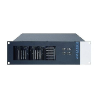
Fig. 56: Front view of power amplifier 4XD250B
Additional information on LED indicators refer to operating instruction (Part No. 798662.GB0).
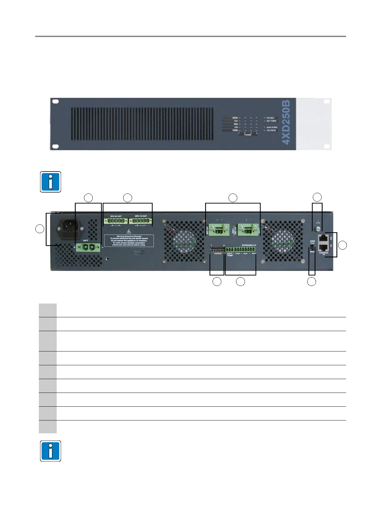
Fig. 57: Rear view of power amplifier 4XD250B
230 V AC rated voltage via IEC power socket and primary fuse T 8 A / 250 V
24 V DC emergency power supply
Plug connections to control unit (use system cable)
The SPK outputs are designed with touch-protected terminals.
2 x output 24 V external
PE connection 0 V and housing
Plug connection – AF input signal from the control unit
GAIN LOW / MAX
EXTENSION L/F
CONFIG - DIP Switch
The described functions depend on the amplifiers required for the specific building.
 Loading...