CHAPTER 12: DESCRIPTION OF PARAMETER SETTINGS
63-4528—04 146
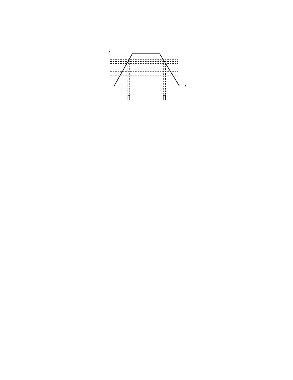
• Once output frequency reaches desired frequency and the corresponding multi-function output terminal is set to 3 or 4 (Pr.02-
13, 02-14, 02-34, and 02-35), this multi-function output terminal will be ON.
02 - 26 Input terminal of I/O extension card (MI10)
02 - 27 Input terminal of I/O extension card (MI11)
02 - 28 Input terminal of I/O extension card (MI12)
02 - 29 Input terminal of I/O extension card (MI13)
Factory Setting: 0
Settings
0: No function
1: multi-step speed command 1
2: multi-step speed command 2
3: multi-step speed command 3
4: multi-step speed command 4
5: Reset
6: JOG command by digital keyboard or external control
7: acceleration/deceleration speed not allow
8: the 1
st
, 2
nd
acceleration/deceleration time selection
9: the 3
rd
, 4
th
acceleration/deceleration time selection
10: EF Input (Pr.07-19)
11: B.B input from external (Base Block)
12: Output stop
14: switch between motor 1 and motor 2
15: operation speed command from AVI1
16: operation speed command from ACI
17: operation speed command from AVI2
18: Emergency stop (Pr.07-19)
19: Digital up command
20: Digital down command
21: PID function disabled
M33625
H
FCMD 60Hz
02-22 40Hz
42Hz
40Hz
38Hz
12Hz
10Hz
8Hz
02-23 2Hz
02-20 10Hz
02-21 2Hz
02-13, 02-14,
02-36, 02-35
02-13, 02-14,
02-34, 02-35
3
4
T
 Loading...


