CHAPTER 12: DESCRIPTION OF PARAMETER SETTINGS
145 63-4528—04
t
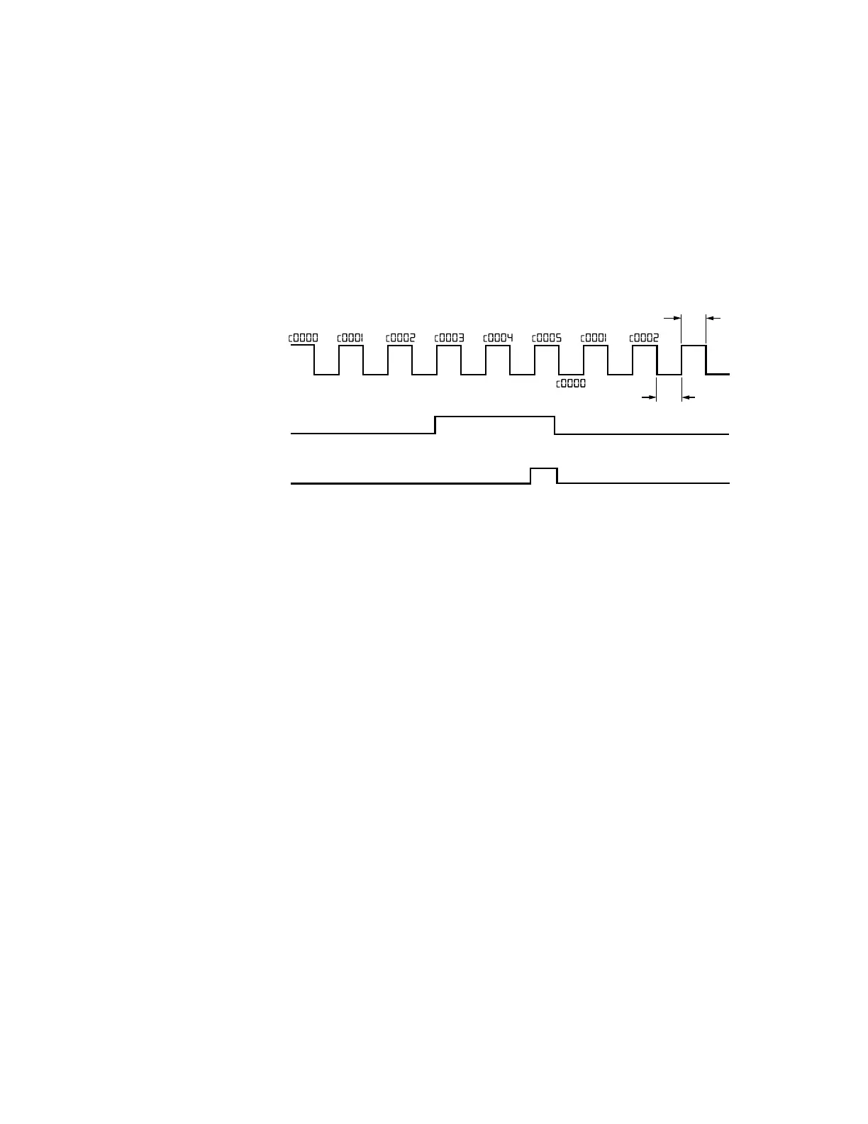
• When the counter value counts from 1 and reaches this value, the corresponding multi-function output terminal will be
activated, provided one of Pr. 02-13, 02-14, 02-34, 02-35 set to 17 (Preliminary Count Value Setting). This parameter can be
used for the end of the counting to make the drive runs from the low speed to stop.
See the sequence diagram below:
• It is used to set the signal for the digital output terminals (DFM-DCM) and digital frequency output (pulse X work period=50%).
Output pulse per second = output frequency X Pr.02-19.
a
02 - 18 Preliminary count value attained (not return to 0)
Factory Setting: 0
Settings 0~65500
a
02 - 19 Digital Output Gain (DFM)
Factory Setting: 1
Settings 1~166
a
02 - 20 Desired Frequency Attained 1
Factory Setting: 60.00/50.00
Settings 0.00~600.00Hz
a
02 - 22 Desired Frequency Attained 2
Factory Setting: 60.00/50.00
Settings 0.00~600.00Hz
a
02 - 21 The Width of the Desired Frequency Attained 1
Factory Setting: 2.00
Settings 0.00~600.00Hz
a
02 - 23 The Width of the Desired Frequency Attained 2
Factory Setting: 2.00
Settings 0.00~600.00Hz
M33624
02-17 5
02-14 17
02-13, 02-14, 02-34, 02-35
02-18 3
TRIGGER SIGNAL
WIDTH
1.0 MSEC
1.0 MSEC
DISPLAY VALUE
[00-04 01]
TRG [02-06 23]
COUNTER TRIGGER
(OUTPUT SIGNAL)
PRELIMINARY
COUNTER VALUE
RY1 PR.02-13 17
TERMINAL COUNTER
VALUE
RY2 PR.02-14 18
 Loading...


