CHAPTER 12: DESCRIPTION OF PARAMETER SETTINGS
63-4528—04 144
• It is for digital input terminal signal delay and confirmation. The delay time is confirmation time to prevent some uncertain
interference that would cause error in the input of the digital terminals. Under this condition, confirmation for this parameter
would improve effectively, but the response time will be somewhat delayed.
• The setting of this parameter is in hexadecimal.
• This parameter is to set the input signal level and it won’t be affected by the SINK/SOURCE status.
• Bit0 is for FWD terminal, bit1 is for REV terminal and bit2 to bit15 is for MI1 to MI14.
• User can change terminal status by communicating.
For example, MI1 is set to 1 (multi-step speed command 1), MI2 is set to 2 (multi-step speed command 2). Then the forward +
2
nd
step speed command=1001(binary)= 9 (Decimal). Only need to set Pr.02-12=9 by communication and it can forward with
2
nd
step speed. It doesn’t need to wire any multi-function terminal.
• The setting of this parameter is in hexadecimal.
• This parameter is set via bit setting. If a bit is 1, the corresponding output acts in the opposite way. For example: If Pr02-13=1,
Relay 1 is open when the drive runs and is closed when the drive is stopped
• The counter trigger can be set by the multi-function terminal MI6 (set Pr.02-06 to 23). Upon completion of counting, the
specified output terminal will be activated (Pr.02-13~02-14, Pr.02-34, 02-35 is set to 18). Pr.02-17 can’t be set to 0.
• When the display shows c5555, the drive has counted 5,555 times. If display shows c5555l it means that real counter value is
between 55,550 to 55,559.
a
02 - 12 Multi-function Input Mode Selection
Factory Setting: 0
Settings 0~65535 (0:N.O.; 1:N.C.)
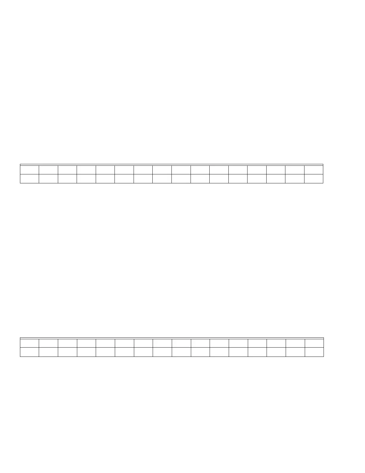
Bit15 bit14 bit13 bit12 bit11 bit10 bit9 bit8 bit7 bit6 bit5 bit4 bit3 bit2 bit1 bit0
MI14 MI13 MI12 MI11 MI10 MI9 MI8 MI7MI6MI5MI4MI3MI2MI1REVFWD
a
02 - 13 Relay1: Multi Output Terminal
Factory Setting: 11
a
02 - 14 Relay2: Multi Output Terminal
Factory Setting: 1
a
02 - 15 Relay3: Multi Output Terminal
Factory Setting: 9
a
02 - 16 Multi-output Direction
Factory Setting: 0
Settings 0~65535 (0:N.O.; 1:N.C.)
Bit15 bit14 bit13 bit12 bit11 bit10 bit9 bit8 bit7 bit6 bit5 bit4 bit3 bit2 bit1 bit0
MO20 MO19 MO18 MO17 MO16 MO15 MO14 MO13 MO12 MO11 MO10 MO2 MO1 ?? RY2 RY1
a
02 - 17 Terminal count value attained (returns to 0)
Factory Setting: 0
Settings 0~65500
 Loading...


