CHAPTER 12: DESCRIPTION OF PARAMETER SETTINGS
143 63-4528—04
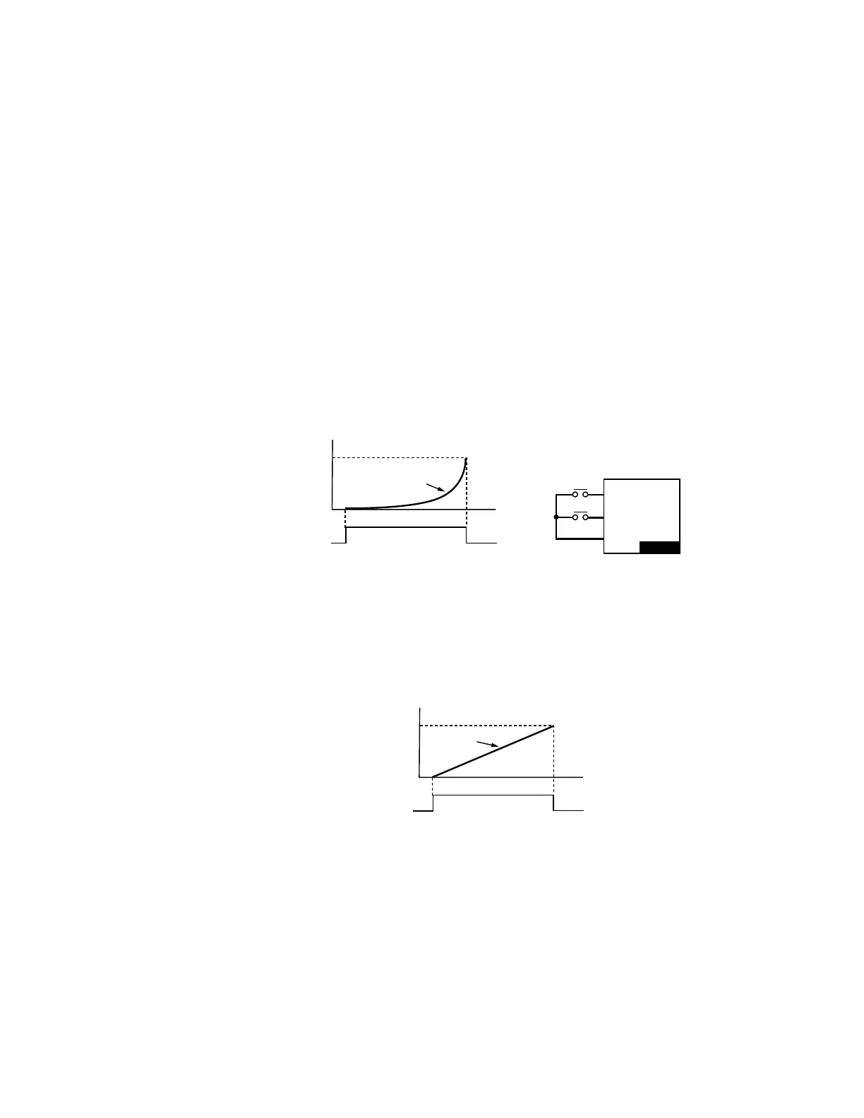
• These settings are used when multi-function input terminals are set to 19 or 20. Refer to Pr.02-09 and 02-10 for the frequency
up/down command.
• When Pr.02-09 is set to 0: press the external terminal UP/DOWN key as shown in the following diagram to increase/decrease
the frequency command (F). In this mode, it also can be controlled by UP/DOWN key on the digital keypad.
• Pr.02-09 set to 1: it will increase/decrease frequency command (F) by the setting of acceleration/deceleration (Pr.01-12~01-
19) and only be valid during operation.
• This parameter is to set the response time of digital input terminals FWD, REV and MI1~MI8.
a
02 - 09 UP/DOWN Key Mode
Factory Setting: 0
Settings 0: UP/DOWN by the accel./decal. Time
1: UP/DOWN constant speed (by parameter 02-10)
a
02 - 10 The Acceleration/Deceleration Speed of the UP/DOWN Key with Constant
Speed
Factory Setting: 0.01
Settings 0.01~1.00Hz/ms
a
02 - 11 MFI Response Time
Factory Setting: 0.005
Settings 0.000~30.000 seconds
M33622
UP
DOWN
TIME
OFFON
EXTERNAL TERMINAL
UP KEY
FREQUENCY
FREQUENCY COMMAND
MI1 ~ 15
MI1 ~ 15
DCM
VFD-CP
M33623
TIME
OFFON
MULTI-FUNCTION
INPUT TERMINAL
10 FREQUENCY
INCREASED COMMAND
FREQUENCY
FREQUENCY
COMMAND
INCREASED BY
ACCELERATION TIME
 Loading...


