CHAPTER 12: DESCRIPTION OF PARAMETER SETTINGS
63-4528—04 142
02 Digital Input/Output Parameter ~ The parameter can be set during operation.
• This parameter is to set the operation control method. There are three different control modes.
02 - 00 2-wire/3-wire Operation Control
Factory Setting: 1
Settings 0: 2 wire mode 1
1: 2 wire mode 2
2: 3 wire mode
02 - 01 Multi-function Input Command 1 (MI1) (MI1) When Pr02-00 is set at “3”:
Three-wire operation control, the terminal M1 becomes the STOP contact
Factory Setting: 1
02 - 02 Multi-function Input Command 2 (MI2)
Factory Setting: 2
02 - 03 Multi-function Input Command 3 (MI3)
Factory Setting: 3
02 - 04 Multi-function Input Command 4 (MI4)
Factory Setting: 4
02 - 05 Multi-function Input Command 5 (MI5)
02 - 06 Multi-function Input Command 6 (MI6)
02 - 07 Multi-function Input Command 7 (MI7)
02 - 08 Multi-function Input Command 8 (MI8)
M33621
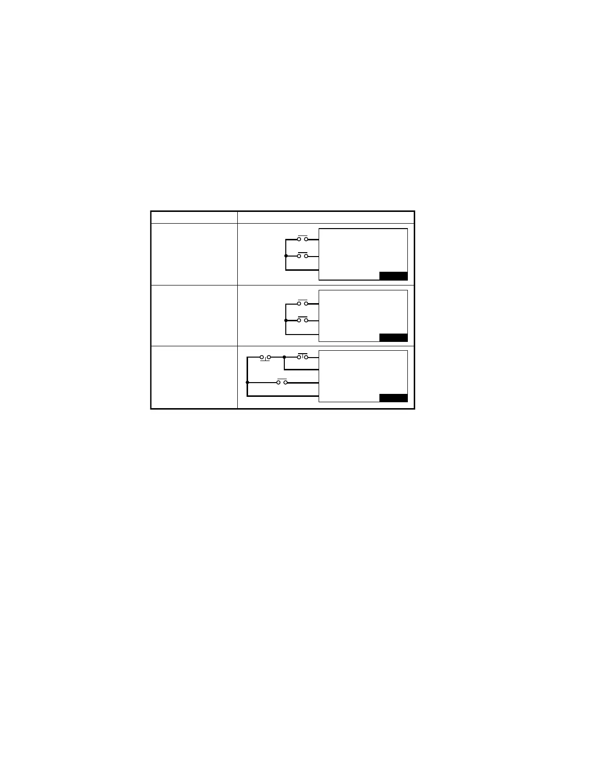
02-00 CONTROL CIRCUITS OF THE EXTERNAL TERMINAL
FWD / STOP
REV / STOP
RUN / STOP
FWD / REV
STOP
FWD: (“OPEN”: STOP)
(“CLOSE”: FWD)
REV: (“OPEN”: STOP)
(“CLOSE”: REV)
DCM
FWD: (“OPEN”: STOP)
(“CLOSE”: RUN)
REV: (“OPEN”: FWD)
(“CLOSE”: REV)
DCM
VFD- CP
FWD: (“CLOSE”: RUN)
MI1: (“OPEN”: STOP)
REV / FWD: (“OPEN”: FWD)
(“CLOSE”: REV)
DCM
RUN
REV / FWD
WHEN THE SETTING IS 0
TWO - WIRE MODE 1
FWD/STOP
REV/STOP
WHEN SETTING IS 1
TWO - WIRE MODE 2
RUN / STOP
REV / FWD
3: THREE - WIRE
OPERATION CONTROL
VFD- CP
VFD- CP
 Loading...


