CHAPTER 12: DESCRIPTION OF PARAMETER SETTINGS
213 63-4528—04
• Computer Link Control by PC or PLC (Computer Link)
• A VFD CORE can be set up to communicate on Modbus networks using one of the following modes: ASCII (American
Standard Code for Information Interchange) or RTU (Remote Terminal Unit).Users can select the desired mode along with the
RS-485 serial port communication protocol in Pr.09-00.
• MODBUS ASCII American Standard Code for Information Interchange: Each byte data is the combination of two ASCII
characters. For example, a 1-byte data: 64 Hex, shown as ‘64’ in ASCII, consists of ‘6’ (36Hex) and ‘4’ (34Hex).
1. Code Description
Communication protocol is in hexadecimal, ASCII: "0", "9", "A", "F", every 16 hexadecimal represents ASCII code. For
example:
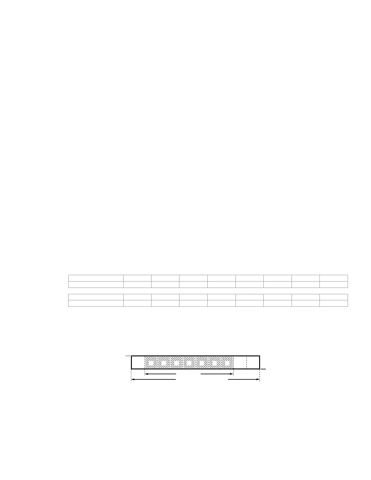
Data Format
10-bit character frame for ASCll
Data Format 7, N, 2
4: 7, E, 2 for ASCII
5: 7, O, 2 for ASCII
6: 8, N, 1 for ASCII
7: 8, N, 2 for ASCII
8: 8, E, 1 for ASCII
9: 8, O, 1 for ASCII
10: 8, E, 2 for ASCII
11: 8, O, 2 for ASCII
12: 8, N, 1 for RTU
13: 8, N, 2 for RTU
14: 8, E, 1 for RTU
15: 8, O, 1 for RTU
16: 8, E, 2 for RTU
17: 8, O, 2 for RTU
Character ‘0’ ‘1’ ‘2’ ‘3’ ‘4’ ‘5’ ‘6’ ‘7’
ASCII code 30H 31H 32H 33H 34H 35H 36H 37H
Character ‘8’ ‘9’ ‘A’ ‘B’ ‘C’ ‘D’ ‘E’ ‘F’
ASCII code 38H 39H 41H 42H 43H 44H 45H 46H
012345
6
M33698
7- DATA BITS
START
BIT
STOP
BIT
STOP
BIT
10- BIT CHARACTER FRAME
 Loading...


