CHAPTER 12: DESCRIPTION OF PARAMETER SETTINGS
221 63-4528—04
For example?
The explanation of exception codes:
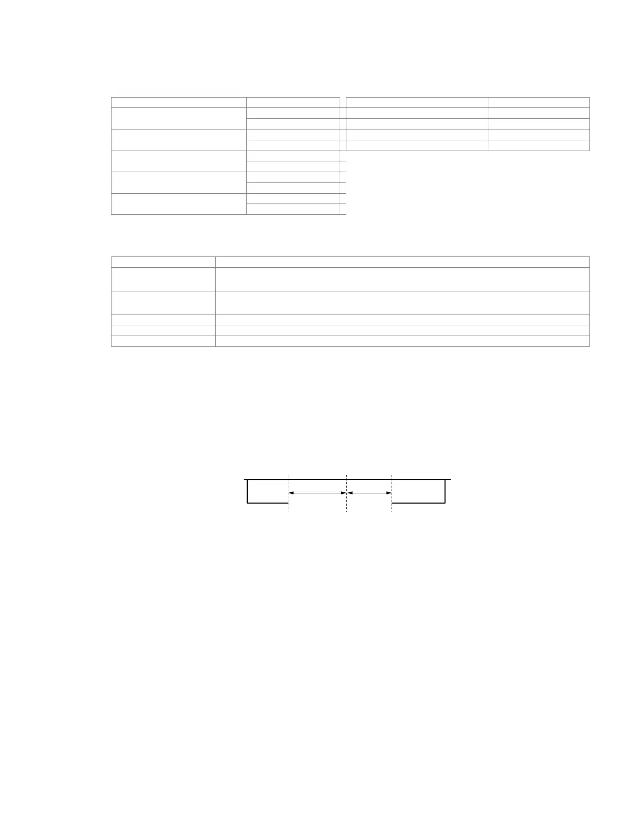
• This parameter is the response delay time after VFD receives communication command as shown in the following.
• When Pr.00-14 is set to 1 (RS485 communication). The VFD will save the last frequency command into Pr.09-06 when
abnormal turn-off or momentary power loss. After reboots the power, it will regards the frequency set in Pr.09-06 if no new
frequency command is inputted
ASCII mode RTU mode
STX ‘:’ Address 01H
Address
‘0’ Function 86H
‘1’ Exception code 02H
Function
‘8’ CRC CHK Low C3H
‘6’ CRC CHK High A1H
Exception code
‘0’
‘2’
LRC CHK
‘7’
‘7’
END
CR
LF
Exception code Explanation
1 Illegal data value:
The data value received in the command message is not available for the VFD.
2 Illegal data address:
The data address received in the command message is not available for the VFD.
3 Parameters are locked: parameters can’t be changed
4 Parameters can’t be changed during operation
10 Communication time-out.
a
09 - 05 Response Delay Time
Factory Setting: 2.0
Settings 0.0~200.0ms
a
09 - 06 Main Frequency of the Communication
Factory Setting: 60.00
Settings 0.00~600.00Hz
a
09 - 07 Block Transfer 1
a
09 - 08 Block Transfer 2
a
09 - 09 Block Transfer 3
a
09 - 10 Block Transfer 4
a
09 - 11 Block Transfer 5
a
09 - 12 Block Transfer 6
M33765
PC OR PLC
COMMAND
RS-485 BUS
HANDLING TIME
OF THE VFD
RESPONSE
DELAY TIME
PR.09-05
RESPONSE
MESSAGE OF
THE VFD
 Loading...


