CHAPTER 12: DESCRIPTION OF PARAMETER SETTINGS
63-4528—04 232
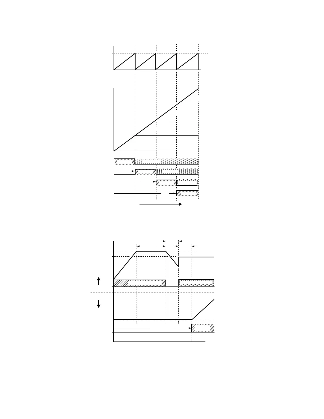
Fig. 4. Sequence of Fixed quantity circulation with PID – Increasing Demand
Fig. 5. Sequence of switching motors at fixed quantity circulation with PID – increasing demands.
However if decreasing demands when flow quantity and pressure are too big, VFD CORE will stop the current operating motors
and wait for the delay time setting of Pr10-04. Then keep on doing this until the last motor stop using mains electricity. See
sequential diagrams in Fig. 6 & 7 below.
FREQUENCY
M33768
DEMAND
DEMAND
INCREASING DEMAND
MOTOR 4
MOTOR 3
MOTOR 2
OUTPUT
(FLOW OR PRESSURE)
MOTOR 1
NEXT MOTOR
STOP MOTOR
OFF
OFF
OFF
TOTAL
OUTPUT
VFD CORE
OPERATIONS
BY DRIVE
BY DRIVE
BY DRIVE
BY DRIVE
MOTOR 4
MOTOR 3
MOTOR 2
MOTOR 1
AC MAINS
AC MAINS
AC MAINS
M33769
FREQUENCY
TIME
0 Hz
MOTOR #2
MOTOR #3
P10-06
MAINS (50Hz)
MOTOR #2 ON MAINS
MOTOR #2 BY DRIVE
MOTOR #3
BY DRIVE
MOTOR #3 OFF
P10-05
P10-03
P10-03
 Loading...


