CHAPTER 12: DESCRIPTION OF PARAMETER SETTINGS
63-4528—04 238
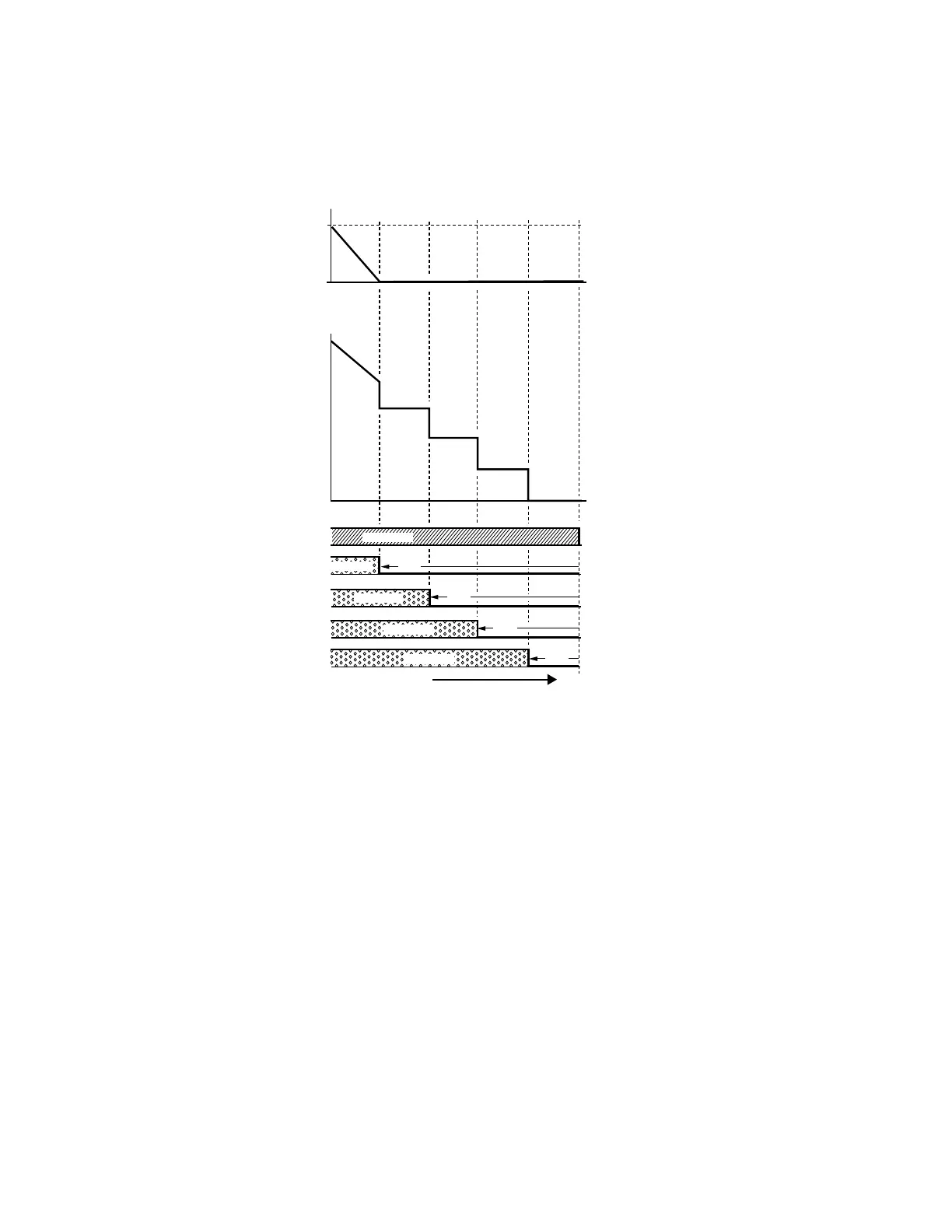
However, if the flow quantity or pressure is too big, VFD CORE will stop, one by one, the motors from using mains electricity until
VFD CORE decrease the main motor’s frequency to 0Hz.
See next two figures.
Fig. 11. Sequence of switching motors at fixed quantity control with PID – decreasing demand.
M33775
FREQUENCY
PUMP MAX
STOP PUMP
DEMAND
DEMAND
DECREASING DEMAND
PUMP 4
PUMP 3
PUMP 2
DEMAND
(FLOW OR PRESSURE)
PUMP 1
PUMP 0
OFF
OFF
OFF
TOTAL
OUTPUT
CP2000
OPERATION
OF FIRST PUMP
BY DRIVE
OFF
AC MAINS
AC MAINS
AC MAINS
AC MAINS
 Loading...


