CHAPTER 12: DESCRIPTION OF PARAMETER SETTINGS
239 63-4528—04
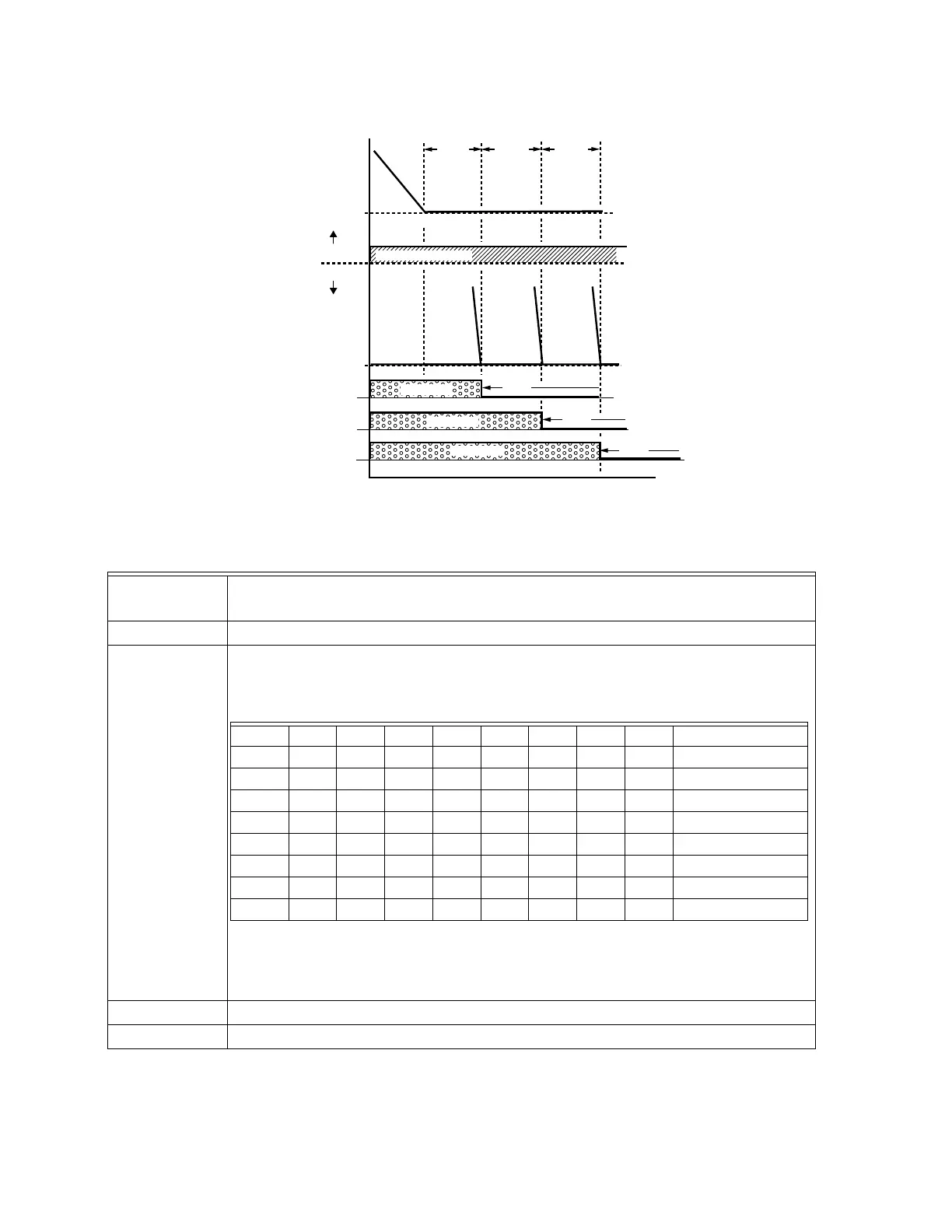
Fig. 12. Sequence of switching motors at fixed quantity control with PID – decreasing demand.
Parameter
setting
Description
P10-00=3
Choose Fixed quantity control
P10-01=X Number of Motors: Maximum 8 motors. After setting number of motors to be connected at the
same time, multi-function output terminals will follow automatically the setting as shown in the
table below.
Table 2: Setting of Multi-function Output Terminal on Circulating Motors
P10-05=X Delay time while fixed quantity circulation at Motor Switching (unit: seconds)
P10-06=X Frequency when switching motors at fixed quantity circulation (Hz)
M33776
FREQUENCY
TIME
PUMP 3
PUMP 2
PUMP 1
0 Hz
OFF
PUMP #0
PUMP #X
PUMP #0 BY DRIVE
OFF
OFF
AC MAINS
AC MAINS
P10-05
MIN
FREQ
P10-05 P10-05
AC MAINS
P10-01 01 02 03 04 05 06 07 08
P02-13 55 55 55 55 55 55 55 55 Motor #1 by Mains
P02-14 56 546 56 56 56 56 56 Motor #2 by Mains
P02-15 57 57 57 57 57 57 Motor #3 by Mains
P02-34 58 58 58 58 58 Motor #4 by Mains
P02-35 59 59 59 59 Motor #5 by Mains
P02-36 60 60 60 Motor #6 by Mains
P02-37 61 61 Motor #7 by Mains
P02-38 62 Motor #8 by Mains
 Loading...


