CHAPTER 6: CONTROL CIRCUIT TERMINAL
31 63-4528—04
RA1 Multi-function relay output 1 (N.O.) a Resistive Load:
5A(N.O.)/3A(N.C.) 250VAC
5A(N.O.)/3A(N.C.) 30VDC
Inductive Load (COS 0.4):
2.0A(N.O.)/1.2A(N.C.) 250VAC
2.0A(N.O.)/1.2A(N.C.) 30VDC
It is used to output each monitor signal, such as drive is in operation,
frequency attained or overload indication.
RB1 Multi-function relay output 1 (N.C.) b
RC1 Multi-function relay common (Relay)
RA2 Multi-function relay output 2 (N.O.) a
RC2 Multi-function relay common (Relay)
RA3 Multi-function relay output 3 (N.O.) a
RC3 Multi-function relay common (Relay)
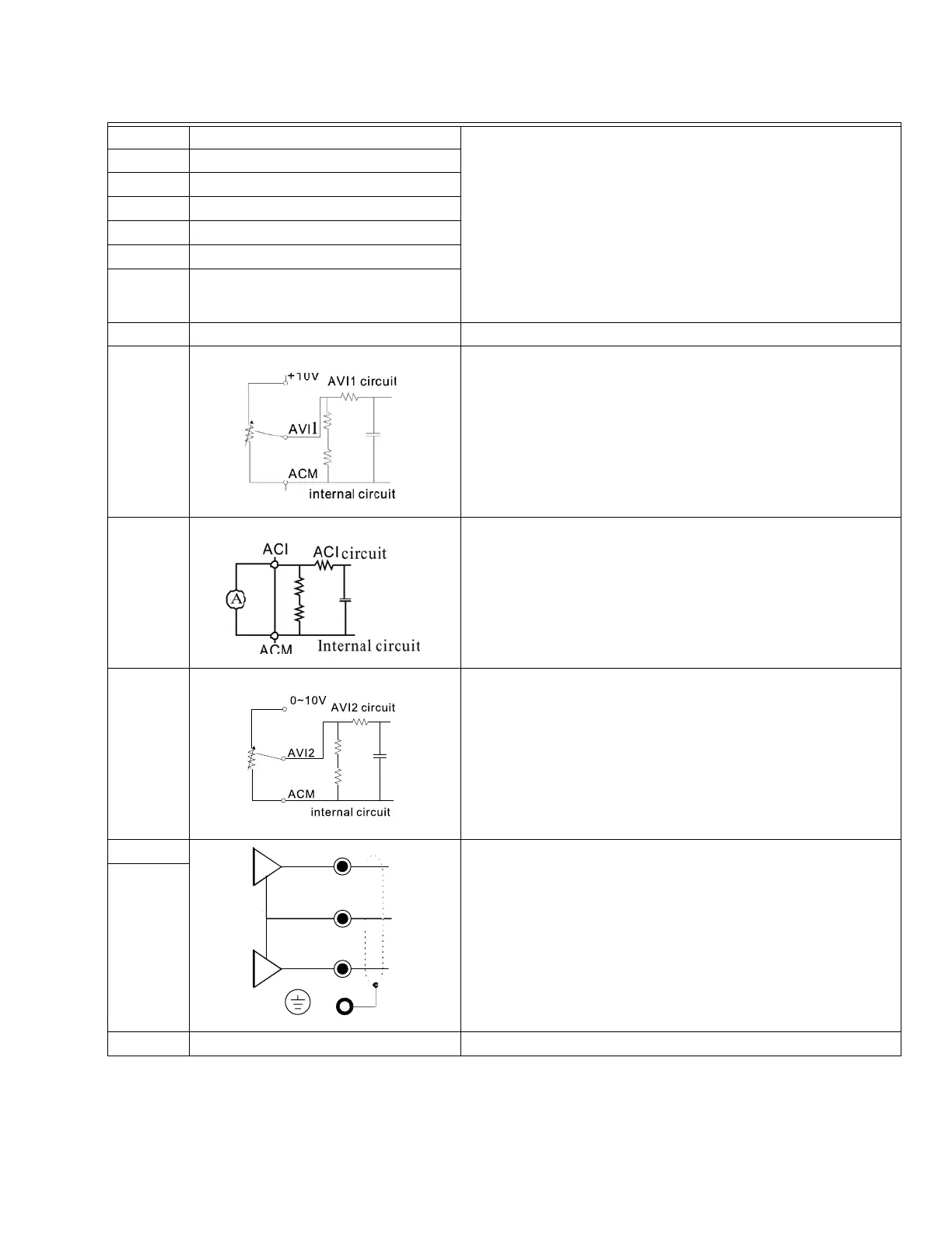
+10V Potentiometer power supply Analog frequency setting: +10Vdc 20mA
AVI1 (AVI)
Analog voltage input
Impedance: 20Ω
Range: 0~ 20mA/0~10V =0~ Max. Output Frequency
(Pr.01-00)
AVI switch, factory setting is 0~10V
ACI
Analog current input
Impedance: 250Ω
Range: 0 ~ 20mA/0~10V=0~ Max. Output Frequency (Pr.01-00)
ACI Switch, factory setting is 0~20mA
AVI2
(AUI)
Auxiliary analog voltage input
Impedance: 20kΩ
Range: 0 ~ +10VDC=0~ Max. Output Frequency
(Pr.01-00)
AFM1
Impedance: 100Ω (current output)
Output current: 20mA max
Resolution: 0~10V corresponds to Max. operation frequency
Range: 0~10V Æ 0~20mA
AFM Switch: factory setting is 0~10V
AFM2
ACM Analog Signal Common Common for analog terminals
Table 1. Control terminal specifications.
M33263
M33265
AFM1
AFM2
ACM
E
 Loading...


