CHAPTER 6: CONTROL CIRCUIT TERMINAL
63-4528—04 32
NOTE: Wire size of analog control signals: 18 AWG (0.75 mm
2
) with shielded wire
Analog input terminals (AVI 1, ACI, AVI 2, ACM)
• Analog input signals are easily affected by external noise. Use shielded wiring and keep it as short as possible [less than 20
meters (65.6168 feet)] with proper grounding. If the noise is inductive, connecting the shield to terminal ACM can bring
improvement.
• This way of using contacts in a circuit should be able to process weak signals at the bifurcated contacts. Do not use contacts
to control the terminal ACM.
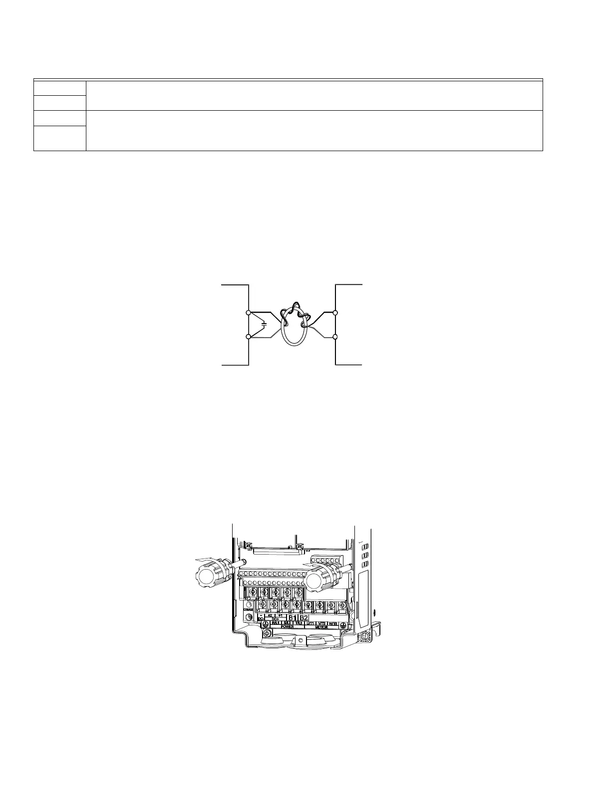
• If the analog input signals are affected by noise from the VFD, connect a capacitor and ferrite core as indicated in the following
diagram.
NOTE: The value of the capacitor is 0.1~0.01uF; if there is no noise issue, the capacitor is not necessary.
Digital inputs (FWD, REV, MI1~MI8, COM)
• When using contacts or switches to control the digital inputs, use high quality components to avoid contact bounce.
Remove the Terminal Block
1. Loosen the screws using a screwdriver (see figure below).
S1
Factory setting: short-circuit
Power removal safety function for emergency stop.
SCM
SG+ Modbus RS-485
PIN 1,2,7,8: Reserved PIN 3, 6: GND
PIN 4: SG- PIN 5: SG+
SG-
Table 1. Control terminal specifications.
M33266
C
ACM
AVI1/ACI/AVI2
FERRITE CORE
M33267