CHAPTER 6: CONTROL CIRCUIT TERMINAL
63-4528—04 30
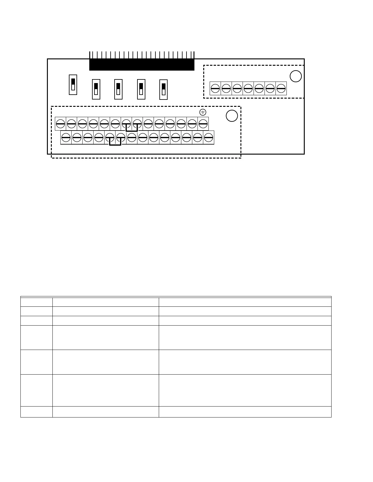
Fig. 1. Removable terminal block.
Control Terminal Specifications
Wire Gauge: 26~16AWG (0.1281-1.318mm
2
)
Screw Torque: (A) 5kg-cm [4.31Ib-in.] (0.49Nm) (As shown in Fig. 1 above.)
(B) 8kg-cm [6.94Ib-in.] (0.78Nm) (As shown in Fig. 1 above)
Wiring precautions:
• Reserve a bare wire strip of 5mm and properly install the wire into the terminal; tighten the installation with a slotted
screwdriver. If the wire is stripped, sort the wire before installation into the terminal.
• Use a flathead screwdriver: blade width 3.5mm, tip thickness 0.6mm
• In the Fig. 1 above, the factory setting for S1-SCM is short circuit. The factory setting for +24V-COM is short circuit and SINK
mode (NPN); please refer to Chapter 4 Wiring for more detail.
Table 1. Control terminal specifications.
Terminals Terminal Function Factory Setting (NPN mode)
+24V Digital control signal common (Source) +24V±5% 200mA
COM Digital control signal common (Sink) Common for multi-function input terminals
FWD Forward-Stop command
FWD-DCM:
ON Æ forward running
OFF Æ deceleration to stop
REV Reverse-Stop command
REV-DCM:
ON Æ reverse running
OFF Æ deceleration to stop
MI1
~
MI8
Multi-function input 1~8
Refer to parameters 02-01~02-08 to program the multi-function inputs
MI1~MI8.
ON: the activation current is 6.5mA 11Vdc
OFF: leakage current tolerance is 10μA 11Vdc
DCM Digital frequency signal common
B
A
0-10V
0-10V
0-10V
0-10V 0-20 mA
0-20 mA0-20 mA
0-20 mA
AFM1 +10V AVI1 ACI DCM +24V +24V COM FWD MI1 MI3 MI5 MI7
AFM1
AFM2 AVI1 ACI 485
Open
RC3 RA3 RC2 RA2 RC1 RB1 RA1
M33261
AFM2 ACM AVI2 ACM DCM REV MI2 MI4 MI6 MI8 SG+ SG-
120
S1 SCM
 Loading...


