CHAPTER 7: OPTIONAL COMPONENTS
63-4528—04 66
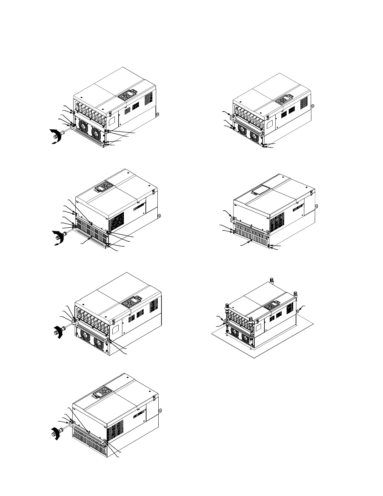
Installation of Flange Mounting Kit Frame D & E
1. Remove 8 screws, then remove Fixture 2
(as shown in the following figure).
5. Tighten 4 screws (as shown in the following figure).
Screw torque: 24~26kg-cm (20.8~22.6Ib-in)
2. Remove 10 screws, then remove Fixture 1
(as shown in the figure below.)
6. Tighten 5 screws (as shown in the figure below).
Screw torque: 24~26kg-cm (20.8~22.6Ib-in).
3. Tighten 4 screws (as shown in the figure below).
Screw torque: 30~32kg-cm (26.0~27.8Ib-in).
7. Place 4 screws (M10) through Fixture 1 & 2 and the plate
then fasten the screws (as shown in the following figure).
Screw torque: 200~240kg-cm (173.6~208.3Ib-in).
4. Tighten 5 screws (as shown in the figure below).
Screw torque: 30~32kg-cm (26.0~27.8Ib-in).
M33388
FIXTURE 1
4
3
1
2
5
10
9
8
7
6
M33391
FIXTURE 2
(4) M10
FIXTURE 1
M33392
FIXTURE 1
1
2
3
4
5
 Loading...


