CHAPTER 8: INSTALLATION OF THE OPTION CARDS
69 63-4528—04
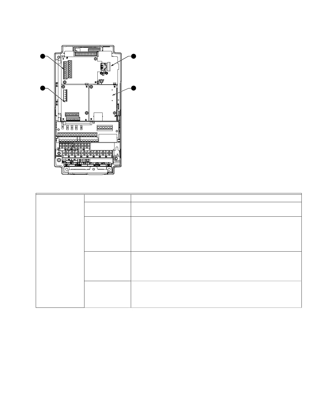
1. RJ45 (Socket) for digital keypad HCRDKEYPAD
• Please refer to CH10 Digital Keypad for more details on the
keypad and optional RJ45 extension cable
2. Communication Expansion Cards (Slot 1)
3. I/O & Relay Expansion Card (Slot 3)
4. No Function
I/O Expansion Card
(4 Digital Input and 4
Digital Output)
Terminals Descriptions
COM
Common for Multi-function input terminals
Select SINK (NPN) / SOURCE (PNP) in J1 jumper/external power supply
MI10~ MI13
Refer to parameters 02-27~02-30 in Chapter 11 to program the multi-function
inputs MI10~MI13.
Internal power is applied from terminal E24: +24Vdc±5% 200mA, 5W
External power +24VDC: max. voltage 30VDC, min. voltage 19VDC, 30W
ON: the activation current is 6.5mA
OFF: leakage current tolerance is 10μA
MO10~MO11
Multi-function output terminals (photocoupler)
Duty-cycle: 50%
Max. output frequency: 100Hz
Max. current: 50mA
Max. voltage: 48Vdc
MXM
Common for multi-function output terminals MO10, MO11 (photocoupler)
Max 48VDC 50mA
SLOT 3
SLOT 2 SLOT 1
M33570
1
2
3
4
 Loading...


