CHAPTER 8: INSTALLATION OF THE OPTION CARDS
63-4528—04 72
Environment Specifications
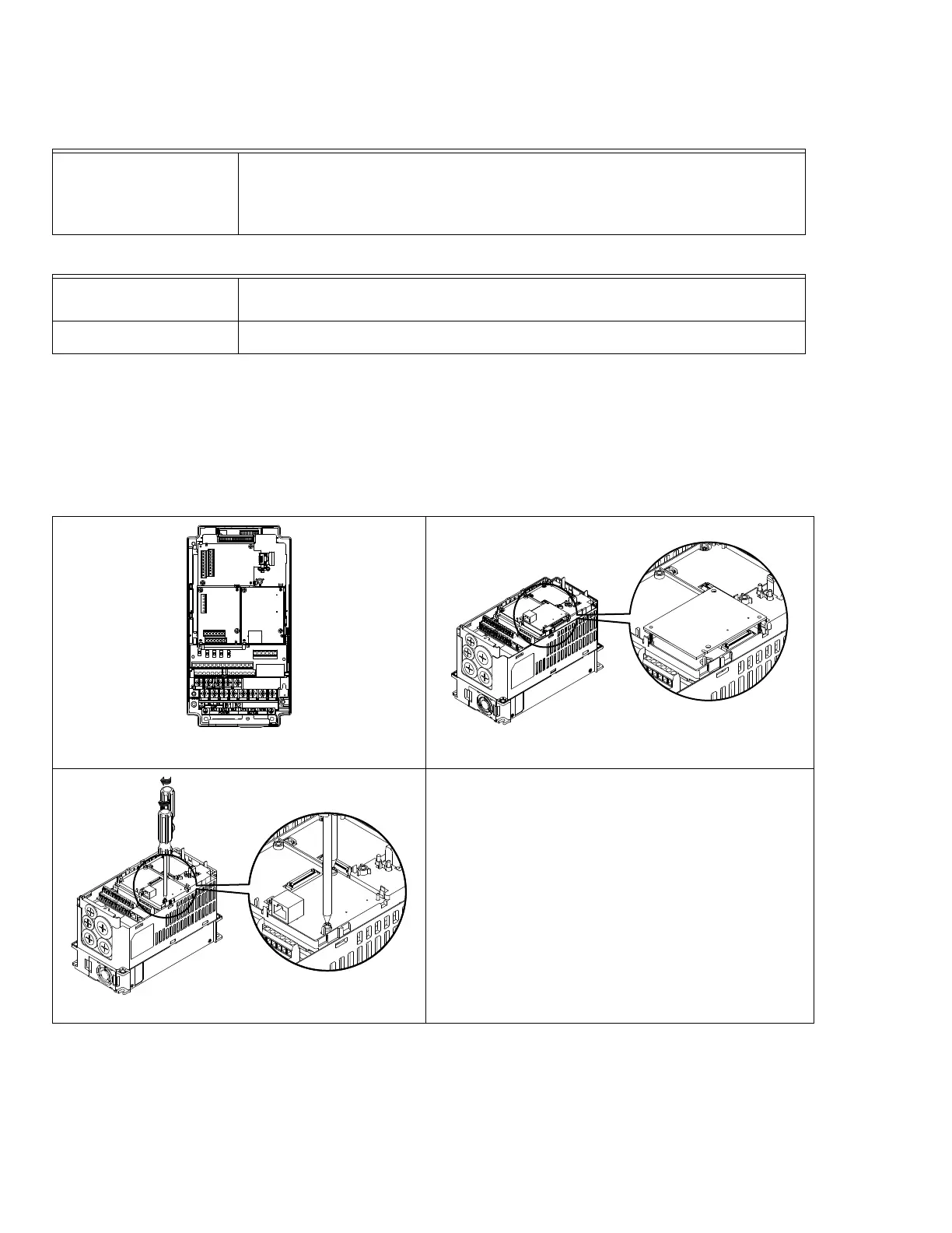
Install MODBUS TCP/IP COMMUNICATION CARD on VFD CORE
1. Switch off the power supply of VFD CORE.
2. Open the front cover of VFD CORE.
3. Place the insulation spacer into the positioning pin at Slot 1 (shown in Figure 3), and aim the two holes on the PCB at the
positioning pin. Press the pin to clip the holes with the PCB (see Figure 4).
4. Screw up at torque 6 ~ 8 kg-cm (5.21 ~ 6.94 in-lbs) after the PCB is clipped with the holes (see Figure 5).
Communication parameter for VFD CORE to connect to an Ethernet
Before VFD-CORE is linked to an Ethernet, set up the communication parameters shown in the table below. Then Ethernet
master will be able to read/write the frequency characters and control characters from/into VFD-CORE after communication
parameters are set.
Noise Immunity
ESD (IEC 61800-5-1,IEC 6100-4-2)
EFT (IEC 61800-5-1,IEC 6100-4-4)
Surge Teat (IEC 61800-5-1,IEC 6100-4-5)
Conducted Susceptibility Test (IEC 61800-5-1,IEC 6100-4-6)
Operation/Storage
Operation: -10°C ~ 50°C (Temperature), 90% (Humidity)
Storage: -25°C ~ 70°C (Temperature), 95% (Humidity)
Shock/Vibration resistance International Standard: IEC 61800-5-1,IEC 60068-2-6 / IEC 61800-5-1,IEC 60068-2-27
[Fig. 3]
[
Fig. 4]
[
Fig. 5]