CHAPTER 8: INSTALLATION OF THE OPTION CARDS
73 63-4528—04
Remove Modbus TCP/IP communication card from VFD-CORE
1. Switch off the power supply of VFD CORE.
2. Remove the two screws (see Figure 6).
3. Twist opens the card clip and inserts the slot type screwdriver to the hollow to prize the PCB off the card clip (see Figure 7).
4. Twist opens the other card clip to remove the PCB (see Figure 8).
CORE
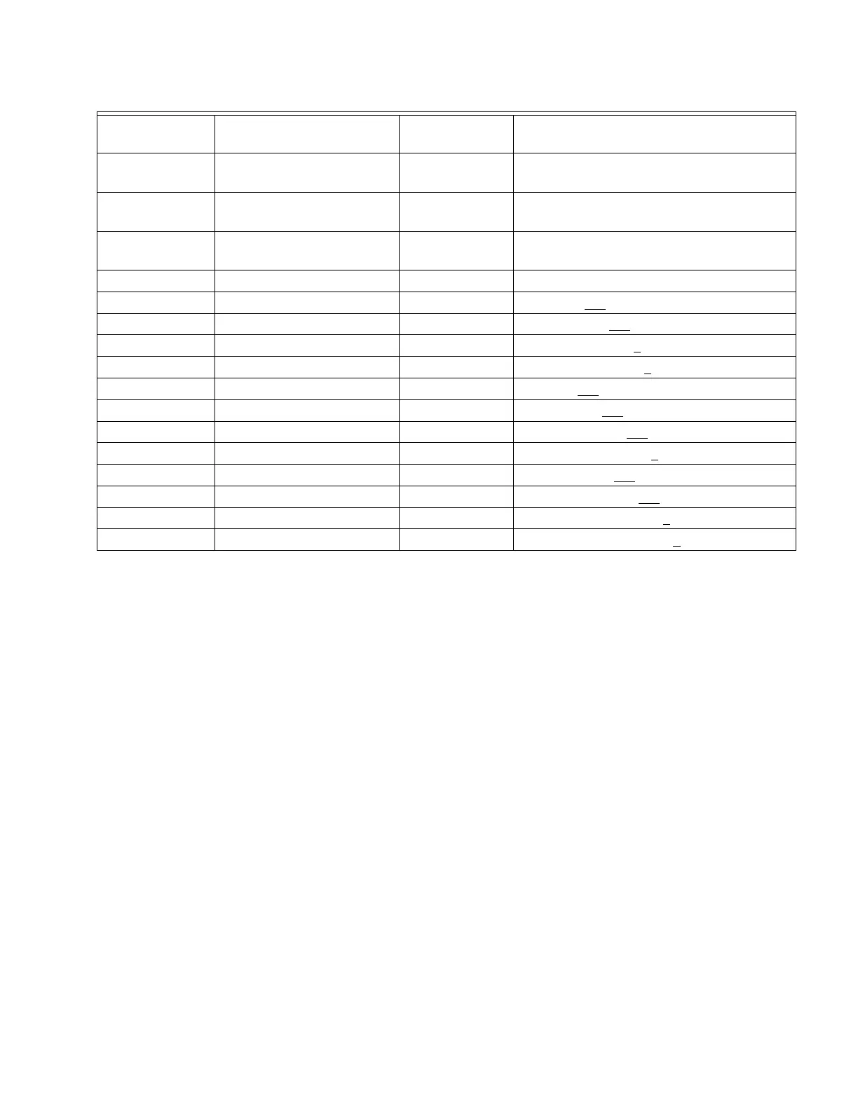
Parameters
Functions
Factory setting
(Dec)
Explanation
00-20
Set up source of frequency
command
0 Frequency command from keypad
00-21
Set up source of operation
command
5 Operation command from communication card.
09-30
Communication decoding
method
0 The decoding method for Honeywell VFD
09-75 IP configuration 0 Static IP(0) / Dynamic IP (DHCP) (1)
09-76 IP address-1 192 IP address 192
.168.1.5
09-77 IP address-2 168 IP address 192.168
.1.5
09-78 IP address-3 1 IP address 192.168.1
.5
09-79 IP address-4 5 IP address 192.168.1.5
09-80 Net mask-1 255 Net mask 255.255.255.0
09-81 Net mask-2 255 Net mask 255.255
.255.0
09-82 Net mask-3 255 Net mask 255.255.255
.0
09-83 Net mask-4 0 Net mask 255.255.255.0
09-84 Default gateway-1 192 Default gateway 192.168.1.1
09-85 Default gateway-2 168 Default gateway 192.168
.1.1
09-86 Default gateway-3 1 Default gateway 192.168.1
.1
09-87 Default gateway-4 1 Default gateway 192.168.1.1