ETHERNET/IP COMMUNICATION CARD
63-4528—04 82
Installation
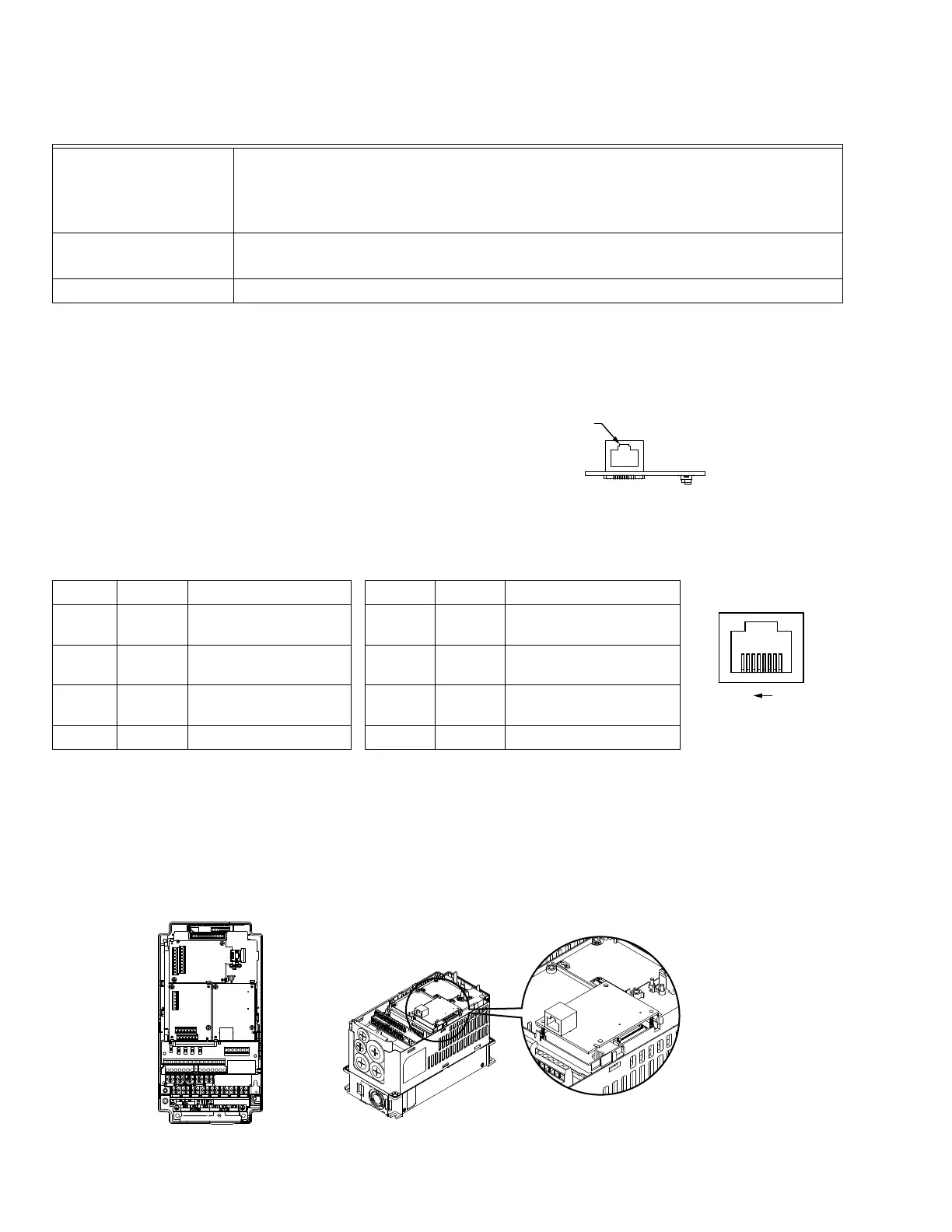
Connecting ETHERNET/IP COMMUNICATION CARD to VFD-CORE
1. Switch off the power of VFD.
2. Open the front cover of VFD.
3. Place the insulation spacer into the positioning pin at Slot 1 (shown in Figure 3), and aim the two holes on the PCB at the
positioning pin. Press the pin to clip the holes with the PCB (see Figure 4).
4. Screw up at torque 6 ~ 8 kg-cm (5.21 ~ 6.94 in-lbs) after the PCB is clipped with the holes (see Figure 5).
Environment Specifications
Noise immunity
ESD (IEC 61800-5-1,IEC 61000-4-2)
EFT (IEC 61800-5-1,IEC 61000-4-4)
Surge Test (IEC 61800-5-1,IEC 61000-4-5)
Conducted Susceptibility Test (IEC 61800-5-1,IEC 61000-4-6)
Operation/storage
Operation: -10°C ~ 50°C (temperature), 90% (humidity), pollution degree 2
Storage: -25°C ~ 70°C (temperature), 95% (humidity), non-condensing
Vibration/shock immunity International standard: IEC 61800-5-1, IEC 60068-2-6/IEC 61800-5-1, IEC 60068-2-27
Connecting ETHERNET/IP COMMUNICATION CARD to a Network
1. Turn off the power of VFD.
2. Open the cover of VFD.
3. Connect CAT-5e network cable to RJ-45 port on ETHERNET/IP
COMMUNICATION CARD.
[Figure 2]
RJ-45 connector: Definition of Pins
PIN Signal Definition PIN Signal Definition
1Tx+
Positive pole for data
transmission
5-- N/C
2Tx-
Negative pole for data
transmission
6Rx-
Negative pole for data
receiving
3Rx+
Positive pole for data
receiving
7-- N/C
4-- N/C 8 -- N/C
RJ45
M33582
8 1
M33584
M33585