ETHERNET/IP COMMUNICATION CARD
83 63-4528—04
Communication parameter for VFD-CORE to connect to an Ethernet
Before VFD-CORE is linked to an Ethernet, set up the communication parameters shown in the table below. Then Ethernet
master will be able to read/write the frequency characters and control characters from/into VFD-CORE after communication
parameters are set.
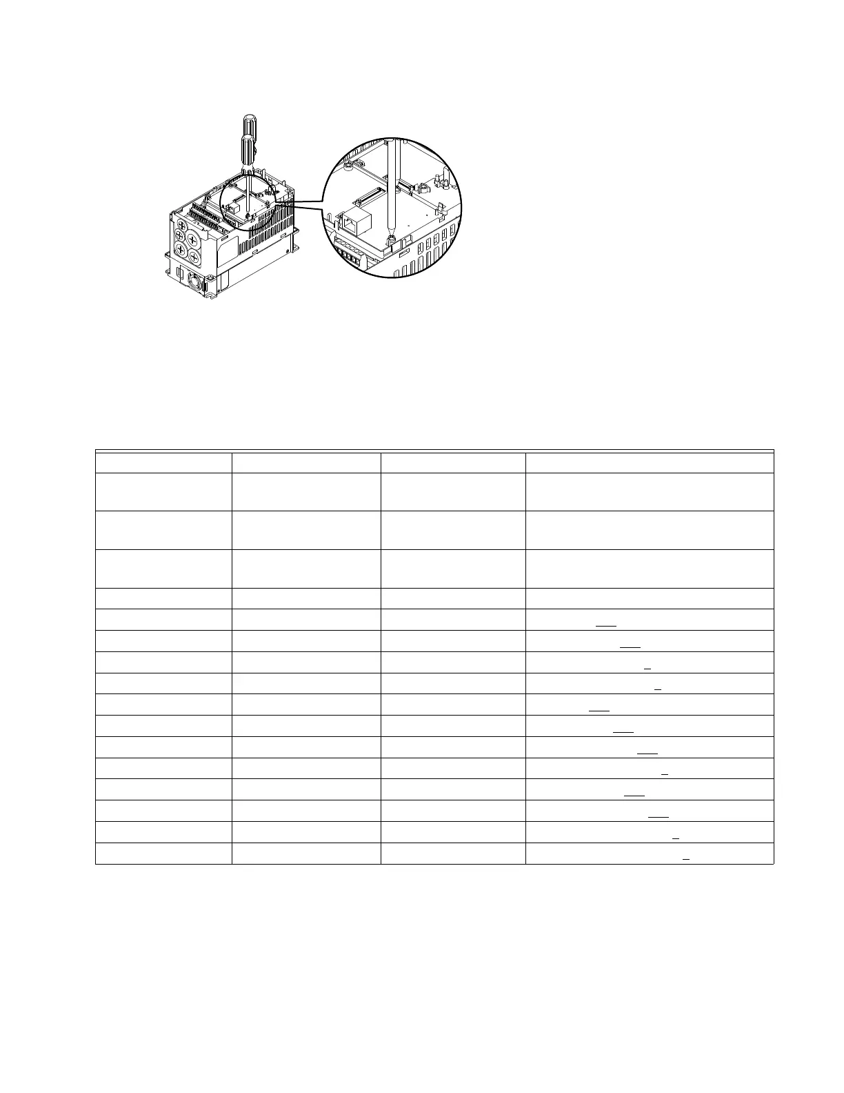
Remove ETHERNET/IP COMMUNICATION CARD from VFD-CORE
1. Switch off the power supply of VFD-CORE.
2. Remove the two screws (see Figure 6).
3. Twist opens the card clip and inserts the slot type screwdriver to the hollow to prize the PCB off the card clip (see Figure 7).
4. Twist opens the other card clip to remove the PCB (see Figure 8).
[Figure 3]
[Figure 4]
[Figure 5]
CORE Parameters Functions Factory setting (Dec) Explanation
00-20
Set up source of
frequency command
0 Frequency command from keypad
00-21
Set up source of
operation command
5
Operation command from communication
card.
09-30
Communication
decoding method
0
The decoding method for Honeywell VFD
(Honeywell AMD).
09-75 IP configuration 0 Static IP(0) / Dynamic IP
09-76 IP address-1 192 IP address 192
.168.1.5
09-77 IP address-2 168 IP address 192.168
.1.5
09-78 IP address-3 1 IP address 192.168.1
.5
09-79 IP address-4 5 IP address 192.168.1.5
09-80 Net mask-1 255 Net mask 255.255.255.0
09-81 Net mask-2 255 Net mask 255.255
.255.0
09-82 Net mask-3 255 Net mask 255.255.255
.0
09-83 Net mask-4 0 Net mask 255.255.255.0
09-84 Default gateway-1 192 Default gateway 192.168.1.1
09-85 Default gateway-2 168 Default gateway 192.168
.1.1
09-86 Default gateway-3 1 Default gateway 192.168.1
.1
09-87 Default gateway-4 1 Default gateway 192.168.1.1
M33575