27
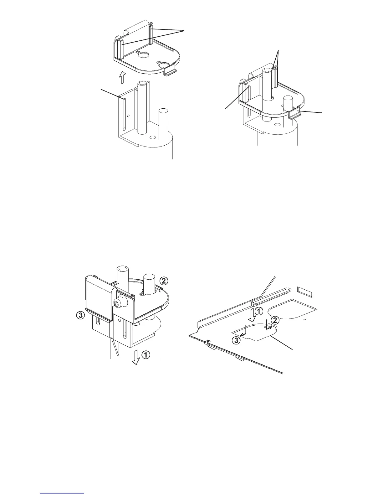
10) Put the FS down into the mounting hole and hook it in position as shown. See Fig.
11. To ensure proper operation, be sure to ¿ t the hook A under the mounting hole.
11) Replace the removed parts in the reverse order of the removal procedure.
12) Plug in the appliance, then move the control switch to the “ICE” position.
Fig. 10
Rail
Rounded end of slot
* Secure here with
screw
When ¿ tted properly, top ends of
bracket and FS are À ush
Screw
Mounting Hole
Fig. 11
Hook A
 Loading...