49
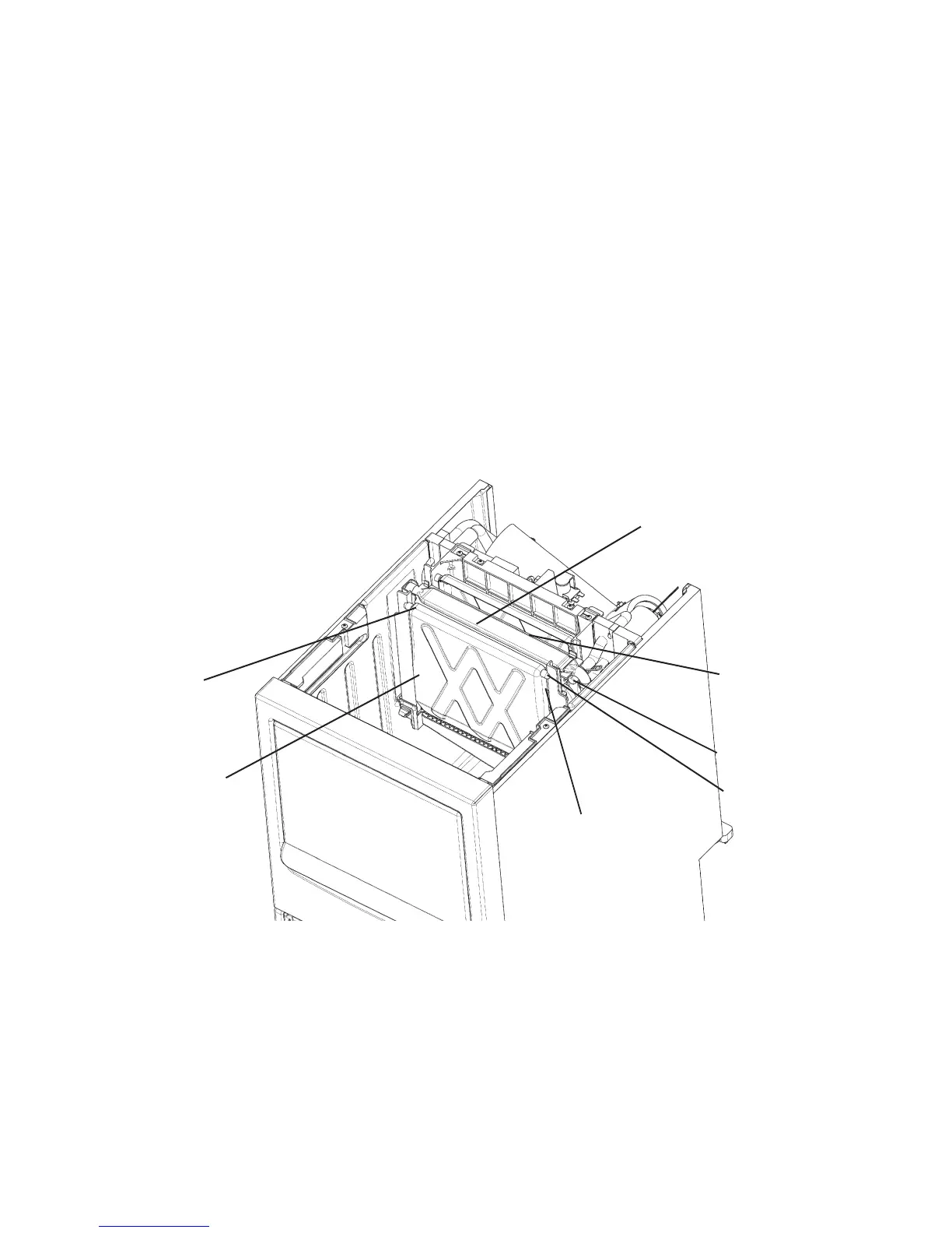
D. Separator
1) Move the control switch to the “OFF” position, then unplug the appliance.
2) Remove the screws at the rear and take off the top panel.
3) Bend the front separator into a U-shape and remove it from the evaporator bracket
shaft. Bend the rear separator into an inverted U-shape and lift it off the evaporator
bracket shaft.
4) Replace the separators in the reverse order of the removal procedure. Check that
the separators are ¿ t correctly on the bracket shafts and can swing freely.
5) Plug in the appliance, then move the control switch to the “ICE” position.
Spray Guide
Spray Tube
Front Separator
Water Supply Tube
Rear Separator
Evaporator Bracket
Fig. 20
Shaft
 Loading...