2-10
Installing the Switch
Installation Procedure
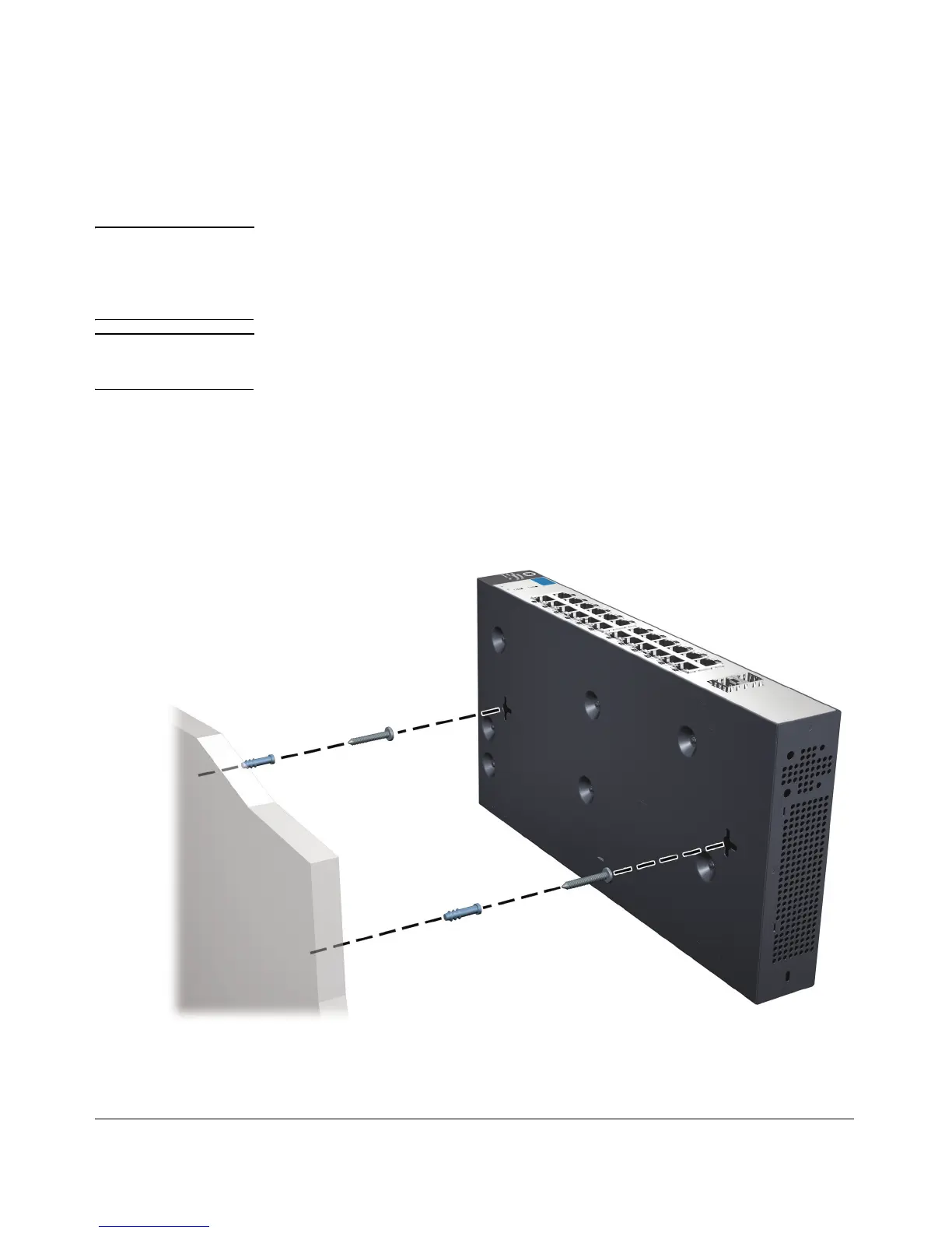
Wall Mounting
You can mount the switch on a wall with the front panel facing up.
WARNING For safe operation, please read the “Installation Precautions” on
page 2-3 and page 2-3, before mounting the switch.
Wall mount the switch with the network ports facing up or down.
Caution The switch should be mounted only to a wall or wood surface that is at least
3/4-inch (19.1 mm) plywood or its equivalent.
1. Install two 5/8-inch (15.875 mm) Number 12 wood screws, (included) into
the mounting surface, positioned 5.5 inches (140mm) apart for the 1810-
8 and 1810-8G Switch, or positioned 10 inches (254 mm) apart for the 1810-
24 and 1810-24G Switch. Use the wall anchors if necessary.
2. Position the switch over the screws, and then slide it down to lock it in
place.

 Loading...